© Rob’s Rails 2019
ROB’S RAILS 
Train-
This review is for the Train-
Credit: I would like to thank David Palmer at DCP Micro/Train-
Apologies in advance for the shaky final video using a web-
This review will be updated with better videos in time.
What is the Smart Screen and what does it do.
The OLED (organic light emitting diode) screen occupies 25mm x 9.5mm of the overall size of the device, which is a mere 31mm long x 9.5mm high x 4.5mm thick. Each screen character block has an amber coloured notional 7 x 5 pixel matrix that is amazingly clear and easy to read even at arm’s length. Upper and lower case letters, as well as numbers 0-
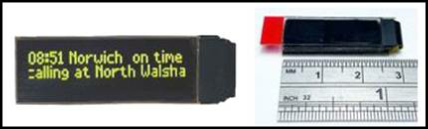
Photo – Train-
The first line shown above, is intended for your message title (say train destination). There are 16 dynamic character blocks across the screen, including 5 character blocks for a live clock, which can be set for any initial time and thereafter it keeps good time until the device is powered down. By dynamic blocks I mean that a 1 or i or l will occupy less block width than an M or W, so the usable line length depends upon what the actual text is.
The second line shown above, auto-
Up to ten separately controlled messages may be programmed.
Examples of the screen text are shown full size in the comprehensive instruction booklet and approximately twice actual size above.
The display is very thin glass and extremely fragile so great care must be taken when handling the device and especially when soldering on the necessary wires to the generously sized contact pads on the back as well as inserting it into a housing. Normal soldering techniques apply when attaching the fine wire leads supplied with the Smart Screen – in and out quickly with a hot iron – as advised in the instructions. The large pre-
The Smart Screen can be used with DCC or DC. In the former case the user will normally program the screen with their own messages of choice, but a DC user has to download and complete the programming planning sheet from the Train-
Train-
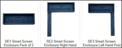
Photo – Train-
The housings are at extra cost. It is advised that once you have soldered on your feed wires that you mount the Smart Screen within such housing for protection against breakage in use.
Pre-
The Smart Screen comes pre-
Train-
Rolling display mode is also your active messages screen default, but this is interrupted by any subsequent live command. Look upon it as you would a PC screen saver.
User Instructions
The instructions packed with the Smart Screen are fairly complex, but very comprehensive and it is advised that you fully read and understood them BEFORE you attempt to reprogram and use the Smart Screen. The instructions comprise seven full pages of text and illustrations in a neat A5 sized booklet, which you will often refer to as you learn how to use the Smart Screen. The instructions in addition to giving general setup information include several projects showing the various ways in which the Smart Screen can be used.
Before you can use the Smart Screen (apart from watching the rolling demo screen, which kicks in as soon as the device is powered up) you have to program it with the messages of your choice allied to a DCC address and how you want to use the device – i.e. which operating mode. Programming messages and setting up addresses is amply covered in the instructions so I will not repeat them here.
Operating modes
There are five operating modes:
1. Controlled by loco direction, Project 1.
2. Sensor or switch controlled, Project 2 and Project 5.
3. Accessory controlled, Project 3.
4. Manual operation from a DCC controller, Project 4.
5. Auto-
In loco direction mode the Smart Screen is told to react to the same address as the ‘rolling stock’ that the Smart Screen is installed in or working with. The Smart Screen shows one message (A) when the train is going forwards and another message (B) when the train is reversed. On-
Sensor or switch mode activates an associated message, such as ‘Train Approaching’ or ‘The next train is for abc calling at xyz’ when a sensor is passed or a manual switch thrown.
In accessory mode there are up to ten screens (A to J), which work in pairs (A-
Manual mode is direct call up of any screen from its associated DCC controller Function button, against the screen’s allocated DCC address, for example Screens A to J are operated via an associated F-
Auto-
How to set up these mode scenarios is fully described in the instruction booklet as Projects 1 to 5, so I will not further expand here.
Programming for use with Hornby Railmaster
The instructions mention using the Smart Screen in conjunction with an Arduino or other similar external system. For this particular review I want to demonstrate how the Smart Screen can be used specifically in conjunction with Hornby’s Railmaster (RM) train control software.
RM can, in addition to manual control of locos and accessories by on-
These programs can be hand written or recorded in real time. In RM we first need to give our Smart Screen an address just like a loco or accessory, and then we can make use of RM’s programs to link our screen messages to other programmed events like operation of locos or points and signals.
We can also just associate our smart screen to a loco or accessory or sensor/switch and operate RM manually.
The screen has been tested by the reviewer and responds correctly in all modes, whether your RM (primary or secondary) DCC controller is a Hornby Elite and/or an eLink.
Loco Mode (Instructions -
For this video clip I simply programmed and linked screens A and B to react to a loco address and then show a short message that changes with loco direction. You may program any message of your choosing for either direction.
Train-
For Accessory Mode (Instructions -
Next I reprogrammed and linked all ten screens (paired A-
Train-
Other Modes – Projects 2, 4 and 5
The screen was tried in the other modes described in the instructions projects section and found to work exactly as expected.
Key Press Programming (Instructions Page 2)
Actual programming of the screen messages requires pre-
Tip: If you aim your webcam at the Smart Screen, you can zoom in large on your PC and also use an expanded throttle in RM to carry out your F-
Summary.
Every modern layout should have one or more of these remarkable UK designed and manufactured display screens. As seen on the brief demonstration video clips they can show any message you like for use on board rolling stock, mounted on station platforms and triggered by various methods, or used outside the railway in model sports stadiums, as shop front and public display screens, or as traffic information boards on motorways and main roads, or as destination boards on buses and trams, etc. The options for use are limited only by your imagination and the size and era of your layout.
Seeing this product on paper does not do it the justice it deserves. You really need to see it in operation to appreciate the capability and clarity of the display, which is why I have included the video clips; unfortunately the mid-
The instructions provided are comprehensive and should be thoroughly read and fully understood in order to make programming of the Smart Screen as easy as possible. You will refer to them often so keep them handy. If you lose them then a download is available from the Train-
A minor drawback is the slightly drawn out message input method, which of necessity has been developed as a very reliable catch all method for the wide variety of Smart Screen users and their various input devices. Normally once you have your Smart Screen fully programmed you won’t be changing it very often, however it is very quick and easy to amend a message if required.
If you also have Hornby’s Railmaster software then Smart Screen can easily be integrated into your layout operations.
My verdict – Train-
R Honnor
Train-
Appendix A
Using a Visual Basic (VB) program to input Smart Screen Messages
Repeated F-
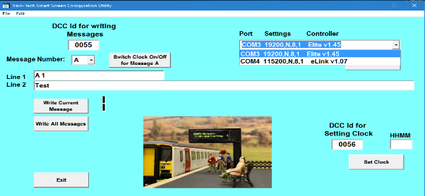
VB Message Writing Interface
We simply pick our Hornby controller with its allocated Com port from the drop down list, and accept the default addresses -
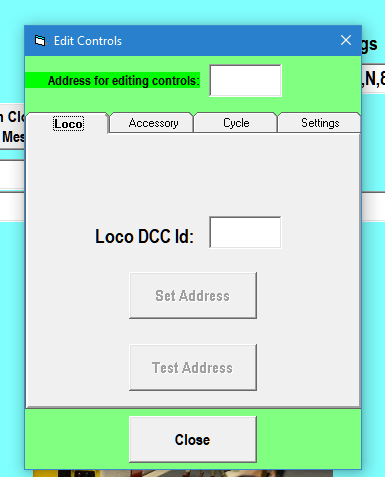
We can also configure the Smart Screen controls using the Controls Menu as seen here…
Loco, or Accessory, or Cycle time and Settings.
This video clip shows the old VB interface writing a single screen message (Screen 1 Message A) in real time, with 100% accuracy.
At present the message writing interface has been tested and guaranteed to work with the Hornby Elite and eLink DCC controllers.
Train-
Ray intends to continue to develop the application. At present it only works with Win 10 and Hornby Elite and eLink controllers. This review will be updated eventually to match any progress.
For now you can download the application from here…
https://1drv.ms/u/s!AhG7bX4H0NOt_VTPajMM54kI0dUt?e=SfCkf2