© Rob’s Rails 2019
ROB’S RAILS 
Testing of Various Relay Modules
This review looks at the use of various multi-
The aim of the test being to prove satisfactory operation of solenoid point motors using a Capacitor Discharge Unit (CDU) for more positive solenoid throw and a Hornby R8247 Point and Accessory Decoder (PAD) as the operational control device.
Three types of modules were reviewed in context:
8-
8-
16-
Introduction
Model railway accessories can be operated manually by way of hand switching or under Digital Command Control (DCC) using PADs as the interface.
It can be advantageous to be be able to combine the two methods, especially to operate solenoid point motors, as the use of DCC often limits the amount of ‘punch’ that can be applied to a solenoid point motor. Use of an external firing circuit can include a hefty CDU to more reliably operate the solenoids. Use of relays allows the DCC PAD to control the relay coil side of things with the external circuit being separately directed through the relay main contacts to the solenoids.
Relay Modules
The following three modules were tested:
8-
8-
16-
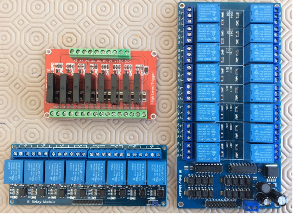
Figure 1 -
The basic wiring schematic used was this:
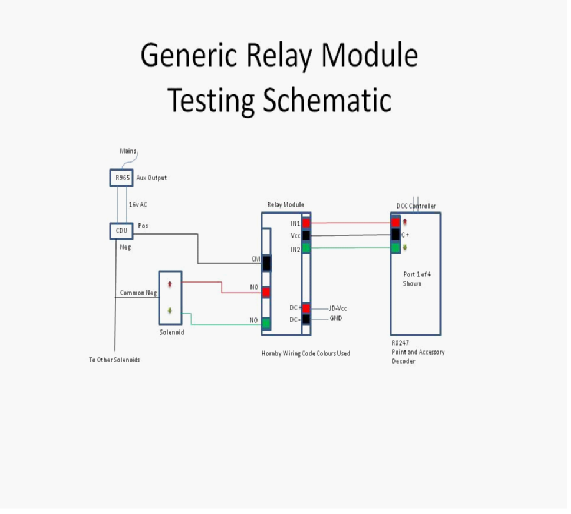
Figure 2 -
General Notes:
1. Not all relay modules have separate JD-
2. Some modules also have jumpers that allow trigger input logic (usually designated IN# or X#) to be switched to -
3. Some SSR modules can be configured to operate either/both AC and DC loads. AC load only modules will have a 2-
SSR Module
This typical 8-
This is the wiring circuit used for this module:
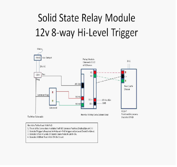
Figure 3 -
Initially the circuit was tested without the CDU or PAD in circuit. This was to prove the AC load functionality. DC IN + and – (JD-
A jumper cable was connected between DC IN + and then X1 and X2 in turn. The associated channel LED indicator lit and the solenoid snapped across. Whilst the jumper cable was held in place the solenoid continued to receive current. Removal of the jumper cable caused the relay to drop out. Normal operation of a solenoid is to provide it with a short burst of power only; else the solenoid coils will burn out. An external timing circuit could be used to connect-
Next the CDU was brought into circuit as shown in the diagram, making the load DC and the test carried out again.
This time there was no response when the jumper cable was applied, however if the jumper was applied before the CDU was brought into circuit then the relay operated the solenoid upon the CDU reconnection. It is thought the charged CDU must affect the internal working of the SSR components.
Again to provide a manual break/make switch into the system defeats the object of the exercise.
The CDU was again removed from circuit and the PAD introduced. PAD provides a negative going pulse on the directional ports with a common positive, hence there was no simple way to configure the PAD to provide a Hi-
Summary
To make SSR modules work with PAD they need to be Lo-
5v 8-
This is the wiring circuit used for this module:
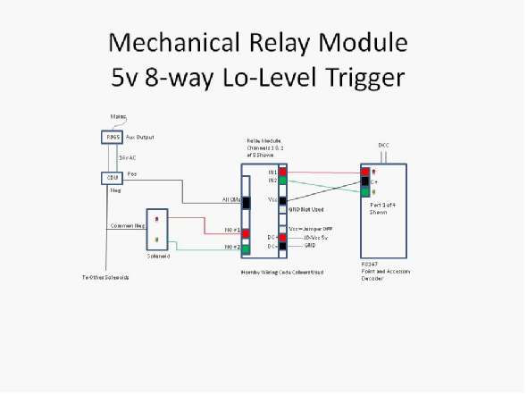
Figure 4 -
This 5v module has a jumper to connect or disconnect JD-
The module was tried with a CDU in and out of circuit and both configurations work.
Summary
The module works with a CDU in or out of circuit. NC contacts are available for use if required.
A disadvantage is having to provide a 5vDC IN power supply. The use of a 12vDC IN module would be better to avoid over-
12v 16-
This is the wiring circuit used with this module:
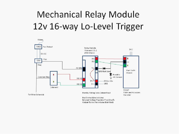
Figure 5 -
This 12v module has a single 12v DC IN (+ and -
It is not known what effect a short 12-
As the module manufacturer had not responded to queries about the effect of using a short 12-
The module manufacturer finally responded about the use of 12-
Summary
Whilst the module works fine as per the diagram with a PAD and CDU, it may benefit from further reliability testing with the PAD C positive also connected into the DC IN circuit to avoid the need for a separate supply and possibly using more than one diode to drop the pulse voltage into Vcc.
Overall Conclusion
A mechanical module is required that has 12vDC relay coils, a separate DC-
A solid state relay module is required to be able to handle AC and DC loads, have Lo-
RH-