This article details the modification of the Hornby surface mounted solenoid point motor to provide a simpler way of connecting the motor to layout wiring.
The wires provided with the motor are short, of fine gauge and easily break off. This modification replaces the wires with a small socket that can be wired with heavier gauge wire more suited to the task of operating a solenoid motor.
Parts required are an industry standard PCB 3-
Caution: The plastic lugs securing the metal base-
ROB’S RAILS 
Article 13 -
© Rob’s Rails 2020
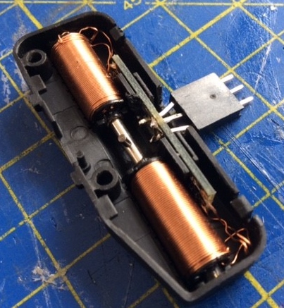
Dismantling and Modification
Carefully ease the plastic clips outwards and slide the base-
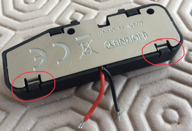
Remove the small bell-
Note the wiring colours attached to PCB -
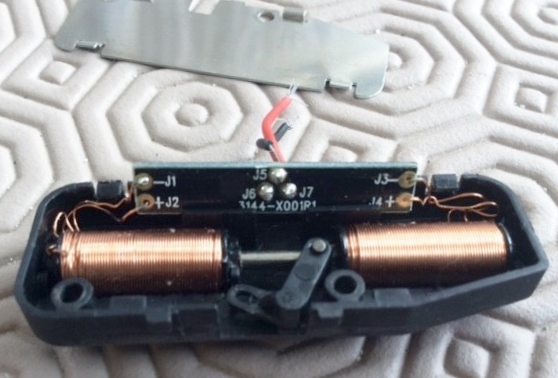
Desolder and discard the existing wires and clear the holes in the PCB with a 1 mm diameter drill bit, taking care not to drift off the hole centre as I have done at J6. Using a fibreglass pencil clean off the PCB tracks to give more soldering grip. Note there is not much space between the tracks around the holes. Whilst the PCB is out of the housing, trim the PCB slot and motor housing as shown to clear the header pins using the socket shape and size as a guide.
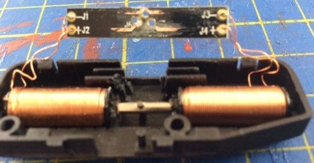
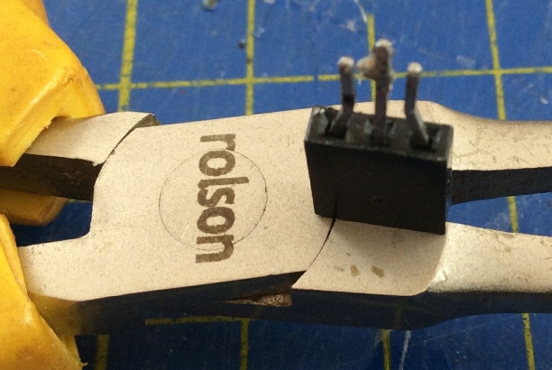
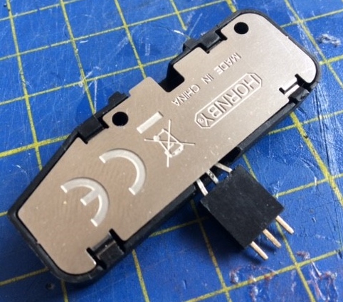
Remove the plastic boss from three header pins as these are not required and push the pins into a 3-
Using the socket as a holding jig, solder the reworked header pins to the holes in the PCB. This is easier with the PCB out of the housing slot. Once soldering is complete, refit the PCB into its slot and check the pins do not interfere with the solenoid core, if necessary trim or adjust to suit. Also check the socket and off the pins smoothly. If not reshape the pins to suit.
At this stage it is wise to check the device operates by briefly touching a 9v block battery against the centre and one outer pin then the other outer pin. The solenoid core should snap across each way.
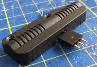
Refit the bell-
You can now install the motor to your layout. The header socket simply pulls off the pins so you can more easily solder it to your points wiring. Heat shrink sleeves are recommended over the solder joints to ensure insulation. The centre pin is the coil common and the outer pins are directional. In the event a motor goes unserviceable it is easily removed without having to mess about desoldering wires or disconnecting at terminal blocks.
Remember when fitting these motors to your layout not to screw them down too tightly or they will jam. Slight movement is recommended.
Although the motors will fit on the inside curve of a point they are best placed on the straight side where they cannot interfere with any low slung loco parts.