The procedure totally dismantles the unit, but you only need to dismantle as much as is necessary to access those parts you wish to work on.
This information is provided in good faith, but as I have no idea of your skill levels it is assumed you know what you are doing and that you work on your RLM at your own risk.
Be aware that opening the case and/or making changes or attempting repairs to this unit will invalidate any warranty on your RLM and may also preclude any future chance of Hornby being able to repair the unit. This also applies to any RLM bought second hand, whether working or not, as the previous owner may have opened the case or attempted repairs.
A common mistake is for users to provide a reverse loop section that is shorter than their longest train, which prevents the RLM working correctly.
The way this unit works is to detect a short circuit as a train passes from the main track into the isolated reverse loop section. The unit immediately switches polarity of the isolated loop to match the main track. As the train leaves the isolated section the RLM again senses and switches to the correct polarity.
The unit can be set for sensitivity by way of the Select/Elite switch -
Top Side

Isolated Track Output Side
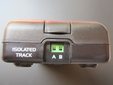
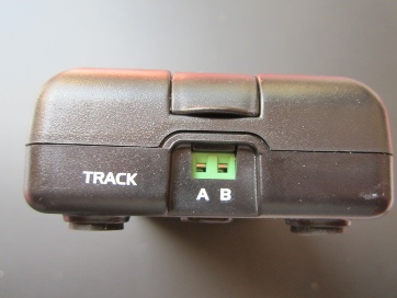
Main Track Connection
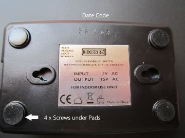
Lower Side
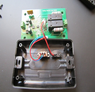
Dismantling:
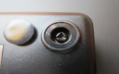
Undo the 4 x security screws found under the 4 x rubber foot pads. These are the usual triangular recess screws.
Lift the top case off. The circuit board lifts out but remains attached to the top case by the switch and led cables which can be disconnected at their plugs.
Reverse side of PCB.
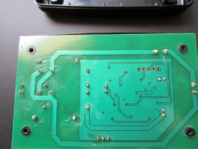
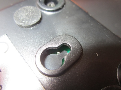
Note one of the component tags on my PCB was visible in the case mounting screw hole and could possibly cause a problem.
Components:
All component codes are clearly visible on the PCB. These are mostly standard components used by Hornby and some have previously been identified in the other Teardown Reports. Refer to the table for identification.
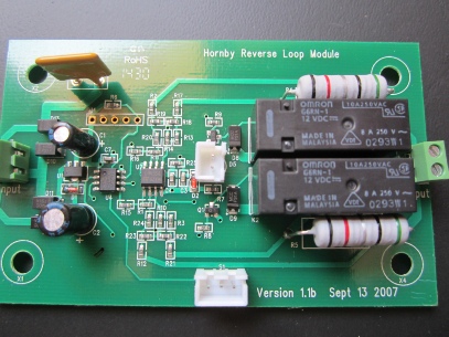
Item Code Description Part Number
F1 Resetting fuse 30V 3A 30R300
K1 & K2 SPDT Relay G6RN-
Q1 & Q8 NPN Transistor SOT23 MMBT5551LT1G
D1 Voltage Regulator Diode 27V 500mW SOD80 BZV55-
D2 Voltage Regulator Diode 2.0V 500mW SOD80 BZV55-
D8-
D5 Red LED 3mm
U1 Voltage Regulator 5V LM78L05ABUTR
U2 Dual Low Power Op Amp SOIC-
U4 PIC12F510 8-
R4 & R5 Wire Wound Resistor 5-
SMD Resistors Size 0603 10k 5k1 4k7 2k2 470R 47k 1k
SW1 SPDT Switch
Problems:
Very little is reported as going wrong with this unit.
Most faults are likely to have been user induced by incorrect connections to the layout, simple as they are (2 wires in and 2 wires out). Reference to the user’s manual will show how to connect the unit and where isolating rail joints need to be.
Acknowledgments:
Many thanks to Ken Wards in the Hornby Research and Development Department for his help in compiling this article.
RH/RLM/May2018/v1.0
ROB’S RAILS -
Hornby R8238 DCC Reverse Loop Module
This report details the procedural teardown of a Hornby Reverse Loop Module (hereafter called an RLM) used to automatically switch track polarity when a train enters a reverse loop. The unit is powered from the main track and outputs the correct polarity to the isolated reverse loop section of track as required.
© Rob’s Rails 2019