The procedure totally dismantles the unit, but you only need to dismantle as much as is necessary to access those parts you wish to work on.
This information is provided in good faith, but as I have no idea of your skill levels it is assumed you know what you are doing and that you work on your power adaptor at your own risk.
Be aware that opening the case and/or making changes or attempting repairs to this unit will invalidate any warranty on your Booster and may also preclude any future chance of Hornby being able to repair the unit. This also applies to any Booster bought second hand, whether working or not, as the previous owner may have opened the case or attempted repairs.
A common mistake is for users to think that this unit can be connected to the same track as the DCC controller, compounded by the Elite controller having Boost terminals.
The way this unit works is to take the DCC signal from the main controller track district (Boost Terminals) and send it to a completely electrically isolated track district. This second (or third or subsequent -
The unit also acts as a reverse loop module in that it will switch the DCC track phasing as and when required.
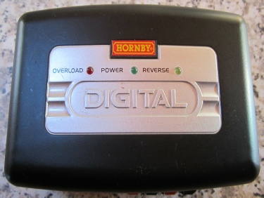
Top
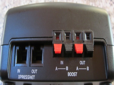
Front Side
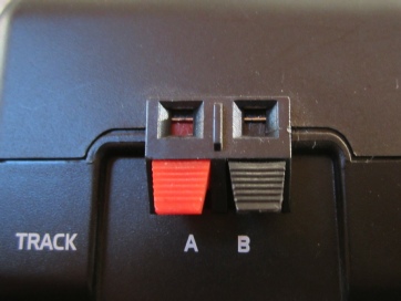
Track Connection
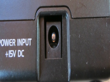
Power Input
Dismantling:
Undo the 4 x security screws found under the 4 x rubber foot pads. These are the usual triangular recess screws.
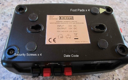
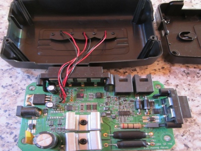
Lift the top case off. The circuit board lifts out but remains attached to the top case by the 3 indicator leds (Red -
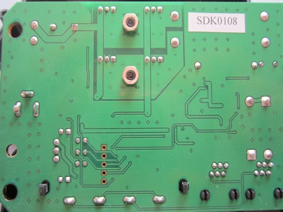
Reverse side of PCB.
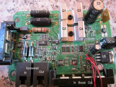
Components:
Main components are marked below. These are mostly standard components used by Hornby and most have previously been identified in the other Teardown Reports.
Item Code Description Part Number
F2 Resetting fuse 30V 5A
L1 & L2 Inductor 7μ0
L4 Common Mode Choke 300R CM3032V301R-
L6 Common Mode Choke 300R CM3032V301R-
D1 & D2 Diode 3A 1N5400
Q1 & Q2 MosFet IRFR024N
Q3 & Q4 Mosfet IRFR9024N
Q5 & Q6 Transistor BC846ALT1G
Q7 MosFet IRF7303
Q8, Q9 & Q11 Transistor BC846ALT1G
Q10 Transistor BC856BLT1G
U5 Regulator 5V LM7805CT
Problems:
Very little is reported as going wrong with this unit apart from output transistors Q1 to Q4, likely due to overheating from loose heat sinks or degraded heat transfer paste. Common mode chokes are known to fail L4 & L6.
Most faults are likely to have been user induced by incorrect connections to the layout. Reference to the user’s manual as stated earlier will show that you can connect this unit to the main power district in several ways. For various reasons it has been found that the most reliable way to power and control a second or subsequent power district is using the method shown in Figure 4 in the manual. You should not attempt to connect the unit by any more than a single method at a time, else damage will occur.
Acknowledgments:
Many thanks to Ken Wards in the Hornby Research and Development Department for his help in compiling this article.
RH/Booster/Jan2018/v1.0
ROB’S RAILS -
Hornby R8239 DCC Signal and Power Booster
This report details the procedural teardown of a Hornby Signal and Power Booster (hereafter called a Booster) used to supply power to and pass DCC control from the master controller to a separate power zone on a layout. The unit is powered by the standard 4-
© Rob’s Rails 2019