The procedure totally dismantles the unit, but you only need to dismantle as much as is necessary to access those parts you wish to work on.
This information is provided in good faith, but as I have no idea of your skill levels it is assumed you know what you are doing and that you work on your accessory decoders at your own risk.
Be aware that opening the case and/or making changes or attempting repairs to these units will invalidate any warranty on your accessory decoder and may also preclude any future chance of Hornby being able to repair or even update the unit. This also applies to any unit bought second hand, whether working or not, as the previous owner may have opened the case or attempted repairs.
The original accessory decoder R8216 was limited to a pulsed output on each of its four ports and required special procedures to pre-
The unit is essentially a CDU (capacitor discharge unit) designed for DCC (Digital Command Control) use. Each port is rated at 200mA steady output, with enough pulsed output to reliably fire a single solenoid point motor, but service experience shows that a pair of solenoids can be fired together such as one would see in a linked cross-
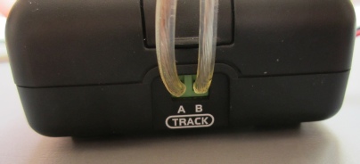
The unit has a DCC signal input on the Track A-
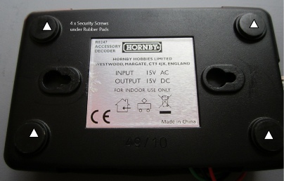
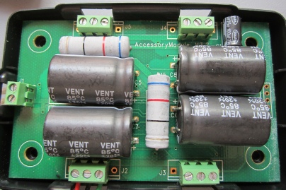
The unit comes apart in the standard Hornby fashion, qty x 4 special screws located under the rubber footpads.
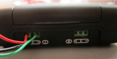
There are very few components, just regular heavy wattage resistors and large capacitors, along with terminal blocks and a jumper area used for update programming of the firmware (not day to day user address programming) on the top side of the PCB.
The underside of the PCB is fairly bare with a dual mosfet (Q1-
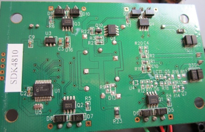
This report is Work in Progress but the information I have to hand is presented for your information in the meantime. Cross reference of board codes to part numbers remains outstanding.
Known Faults
Short circuits on track can cause a decoder to lose its addressing requiring a reset and re-
There is one known serious failure mode due to a past bug in the Select controller which is only seen at firmware version 1.1 but can cause an R8247 to fail. The problem is not seen with the Select at other firmware revision states or with other controllers.
The Select v1.1 bug scenario is this:
If port 1 is activated the R8247 will start to pulse on/off rapidly. If a point motor is connected to the port it will discharge the on-
If the unit is powered down port 1 will reset and the unit will work fine until port 1 is accessed again. If any other ports are selected first then the unit will work until port 1 is next used whereupon the unit fails again.
If the system is left powered in the failure state it is possible for the output transistors to fail completely. The pulsing is not easy to detect and the chance of final failure makes diagnosis also difficult.
The main problem is the R8247 can be repaired or replaced only to fail again as the Select v1.1 bug is the root cause.
The best advice is never to connect an R8247 to a Select at revision 1.1. Get the Select upgraded instead. You may be able to get this done free of charge by Hornby (contact Customer Services) and you may also be able to claim for a new R8247 if the problems are proven to be connected.
Beware buying second hand R8247 units as they may have been damaged by the Select bug and sold on possibly defective.
There is a fault in the R8216 firmware that means when certain high number points addresses are used the complementary lower numbered addresses also fire. Investigation and reprogramming to fix this fault in an obsolete unit is unlikely so just avoid using any point address numbers that clash.
Acknowledgments:
Many thanks to Ken Wards in the Hornby Research and Development Department for his help in providing part numbers for the circuit board codes quoted in this article.
RH/Acc-
ROB’S RAILS -
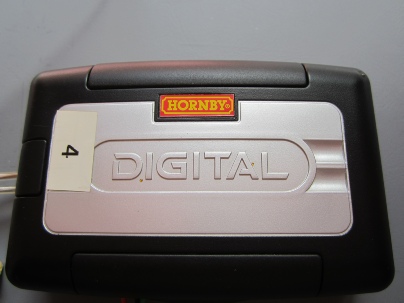
Hornby R8216/R8247 Accessory Decoders
This report details the procedural teardown of a Hornby Accessory Decoders, highlights any parts that are known to have gone faulty, tells of their physical circuit board code, identifies their original part number and where applicable provides an equivalent part by supplier code.
Version 2.0 is physically identical but provides for Standard and 2 Special operating modes giving added functionality.
© Rob’s Rails 2019