The procedure totally dismantles the unit, but you only need to dismantle as much as is necessary to access those parts you wish to work on.
This information is provided in good faith, but as I have no idea of your skill levels it is assumed you know what you are doing and that you work on your HM2000 at your own risk.
Be aware that opening the case and/or making changes or attempting repairs to this unit will invalidate any warranty on your HM2000 and may also preclude any future chance of Hornby being able to repair the unit. This also applies to any unit bought second hand, whether working or not, as the previous owner may have opened the case or attempted repairs.
Warning:
This device contains components at 240VAC UK mains voltage, which is a lethal potential.
Making alterations or repairs to UK mains operated equipment must be carried out by a competent person as defined by the Law.
Other countries may have similar legislation -
Opening this unit is at your own risk.
This article covers the early design HM2000 up to around 2015 after which the internal circuitry changed. There are several versions, some with the large mains input lead shown here, some with a smaller figure-
Dismantling:
Remove the 3 x security screws in the forward edge of the lower case – these screws have a triangular recess requiring a special bit.
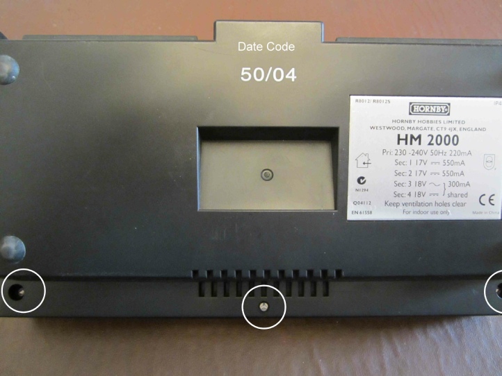
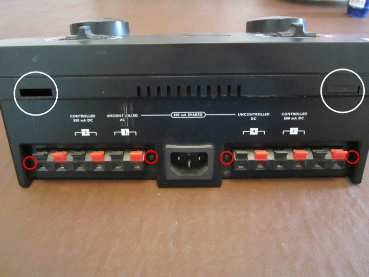
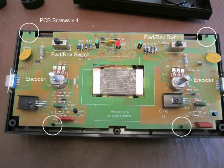
Do not remove the 4 x small cross point screws either side of the rear panel terminal blocks (circled red in the picture). These screws have semi-
Note the 2 pairs of unmarked outer terminals are not connected and are reserved for future development. Later units have a mains on/off switch and/or a smaller mains lead.
Note the tabs (circled in white below) engaging the top case to the lower case -
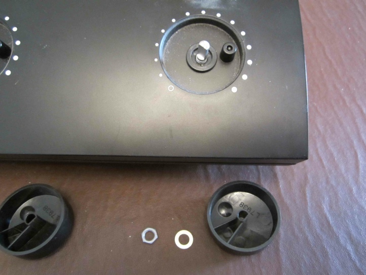
Remove the speed knobs but pulling upwards – some form of flat bladed lever may be required to help with this. Remove the nut and washer from each spindle. Note the peg on the case recess and the stops inside the knob. These limit the knob rotation. There is also a bush around the spindle which may dislodge as the case is removed.
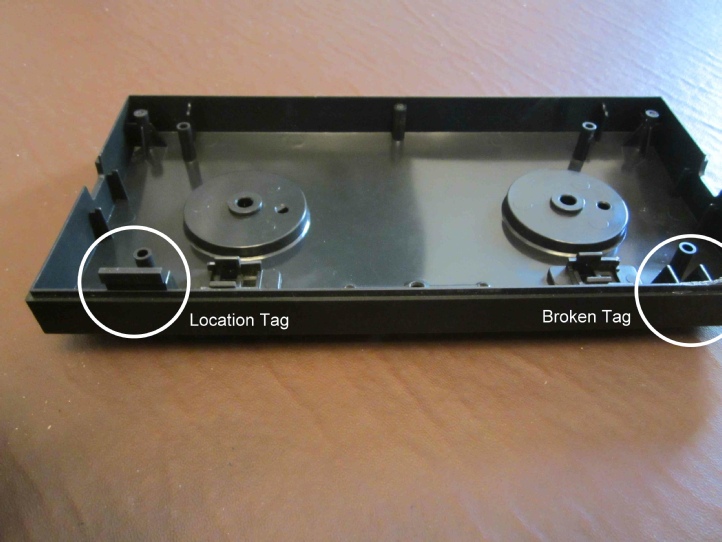
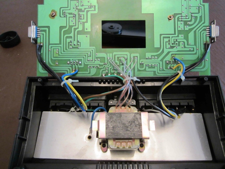
The top case can be rotated away from the lower case taking care not to break the fragile tags at the rear edge of the case -
The circuit board is attached with 4 x small cross point screws and rotates clear but remains attached by wiring to the terminal blocks. Be very careful as some of the wires attached to the transformer are fragile and if dislodged will require specialist help by a qualified electrician certified to work on UK mains equipment.
The transformer is attached by 4 cross point screws and lifts away together with the aluminium heat spreader plate (fitted to alleviate hot spots for certain approval requirements but not found on pre 2003 units) -
The picture below shows that most items on the circuit board are identified by part number, so I will not list them again.
Faults:
This is a robust unit and generally totally reliable but an often reported fault on the forums is non linear speed control and this suggests wear of the encoders, which may require replacement. Note that they have an Off switched position if ordering replacements. This off click can become less than positive requiring a replacement item.
Debris can collect under the speed control knobs causing rough operation. Remove the knobs and clear any debris.
The unit has qty x 2 PTC, an RXE185 (1.84A 0.1 Ohms) and an RXE135 (1.5A 0.15 Ohms).These are low resistance at room temperature but can get very hot and cut off at low loads. Replacement is the only fix. You can measure the resistance of a good one for reference later if a fault develops.
In event an PTC fails it may take out the associated diode(s), easily seen by the burn marks. Replace with any 1A 400V or better component.
There have been the occasional SCR failures and even more rarely the change over switch have failed. Again replace with a like component.
Reassembly is the reverse of dismantling, but care must be taken to avoid damage to the wiring and to correctly engage the Fwd/Rev sliders on the top case with their associated change over switches on the circuit board. Also take care not to dislodge the plastic bush around the encoder spindles.
Acknowledgments:
Many thanks to Ken Wards in the Hornby Research and Development Department for his help with this article.
RH/HM2000/v.1.0.2/May2019
ROB’S RAILS -
Hornby R8012/R80125 HM2000 DC Controller
This report details the procedural teardown of a Hornby HM2000 Dual DC Controller. The majority of components are adequately identified on the circuit board.
© Rob’s Rails 2019