The procedure totally dismantles the unit, but you only need to dismantle as much as is necessary to access those parts you wish to work on.
This information is provided in good faith, but as I have no idea of your skill levels it is assumed you know what you are doing and that you work on your Elite at your own risk.
Be aware that opening the case and/or making changes or attempting repairs to this unit will invalidate any warranty on your Elite and may also preclude any future chance of Hornby being able to repair or even update the unit. This also applies to any Elite bought second hand, whether working or not, as the previous owner may have opened the case or attempted repairs.
Dismantling:
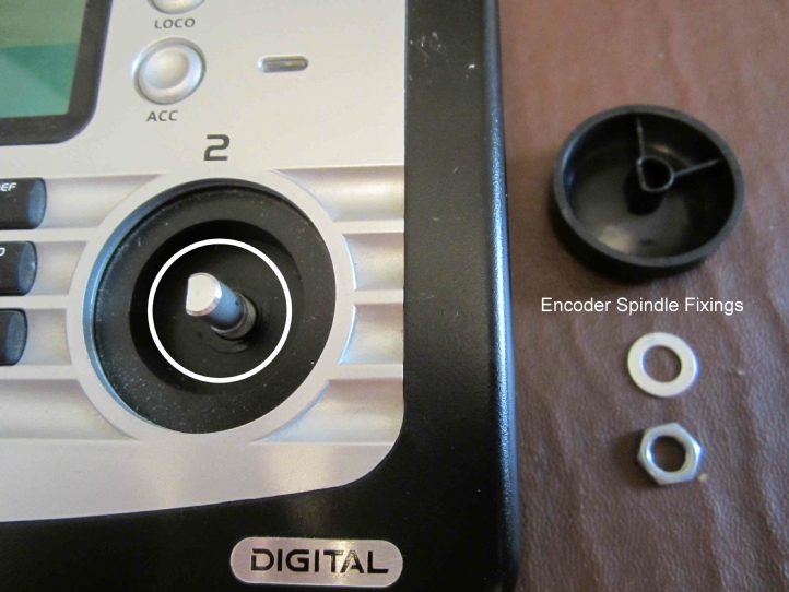
At the front of the unit pull off the qty 2 encoder (speed control) knobs, then with a box spanner remove the nut and washer from each encoder spindle.
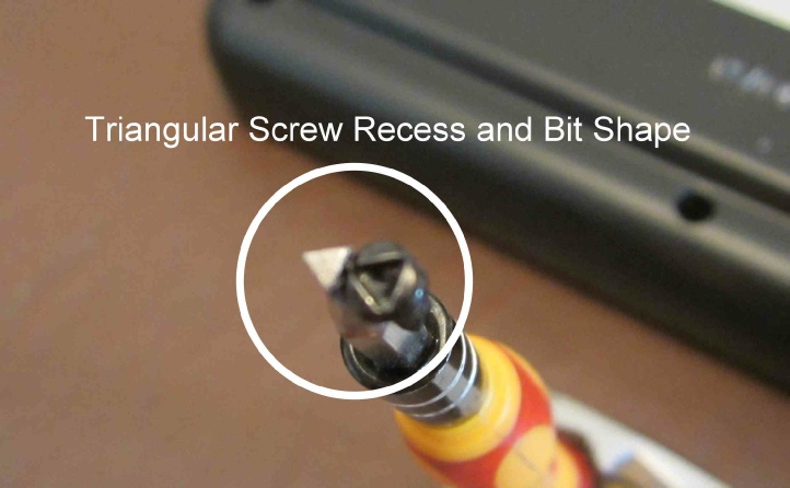
The lower case is held to the top case by qty 11 special screws as illustrated – qty 5 recessed deep in the lower case – qty 4 in the terminal board back face of the case and a further qty 2 attaching this back face to the top case.
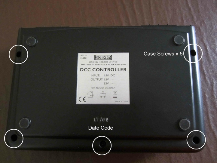
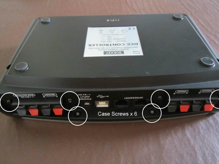
These screws have a triangular recess, hence a special screwdriver bit is required, although at a push a hex-
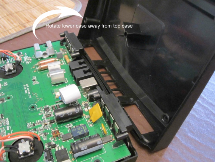
Once released lift away the lower case by rotating it clear of the terminals in the top case.
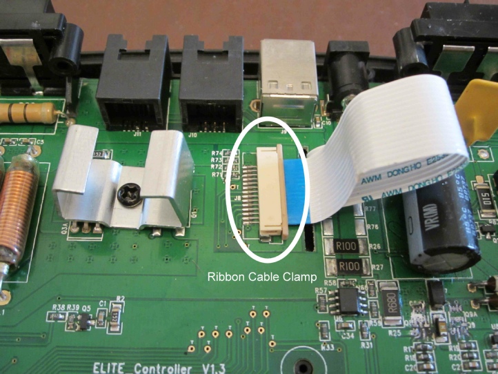
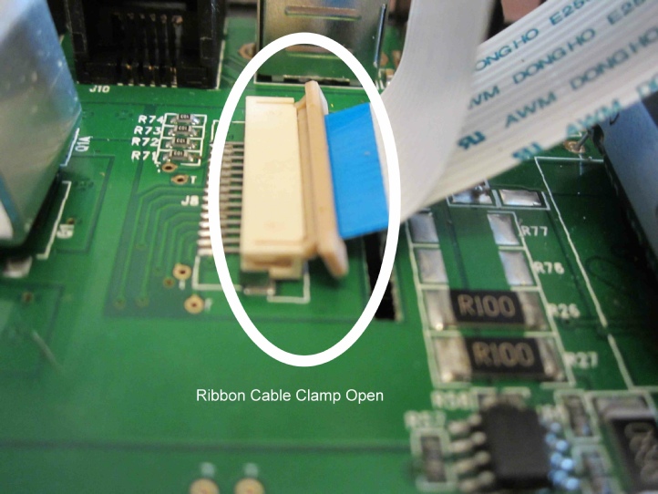
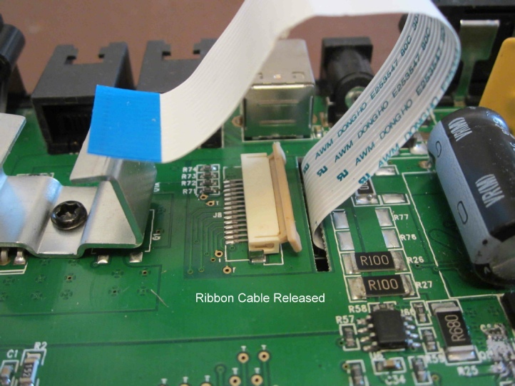
Next release the ribbon cable clamp by easing the beige locking bar away from the white socket with a thin blade screwdriver until the ribbon cable comes free.
There are qty 2 clips holding the motherboard into the upper case.
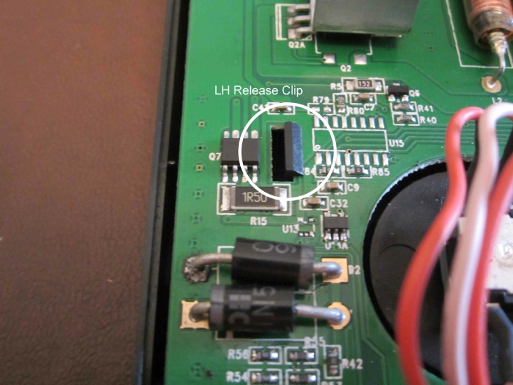
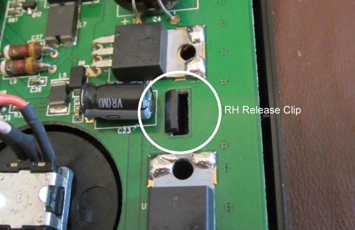
Press each clip outwards whilst easing the motherboard up off its locating pegs. The motherboard will lift free but take care to ease the ribbon cable out of the slot as you do so.
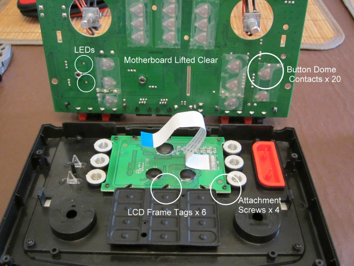
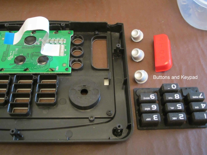
Turning the motherboard over reveals triangular dome contact plates that the buttons operate. These are only secured to the motherboard by sellotape so be careful not to disturb them. If you are having problems with buttons not working, then the problem will likely be with these dome contacts. Slight corrosion due to periods of inactivity prevents good contact, but the action of operating the buttons and the domed shape of the contacts mean they self clean when used, so repeated button presses should fix the problem without dismantling.
The buttons just lift out of the top case but take care with the numerical pad as it can dismantle itself and is fiddly to reassemble if it does.
The display screen daughterboard is attached to the case by qty 4 small cross point screws. Once removed the screen module just lifts out.
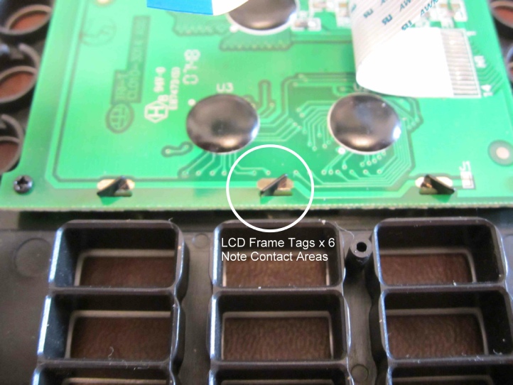
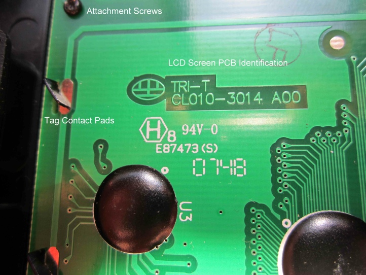
If you have had a screen problem the fault may either be with a badly seated ribbon cable or by a disturbed or just plain dirty elastomeric (zebra) connectors, which pass the board data to the LCD screen. To get at these connectors carefully turn the qty 6 tags securing the screen frame to the board using a pair of pliers until they align with the board slots.
Note: As shown in the picture how the tags make contact with the daughter board PCB track – take care to stay within these pads later when you twist the tags back to re-
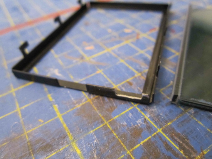
You can then lift the metal frame away from the screen. Note the frame shown has already been modified by filing an additional slot for the back-
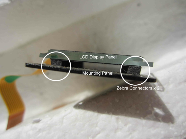
The LCD screen is only held on by pressure bonding of the zebra connectors to the screen and the circuit board so carefully prise it all apart. This picture shows the Select LCD but the Elite is similar once the frame is removed.
Clean up all associated parts with IPA (isopropyl alcohol) and importantly allow to thoroughly dry before reassembly. Keep IPA away from the edge of the LCD in case it seeps into the layers and smears the display.
The display does not have a back-
Reassembly -
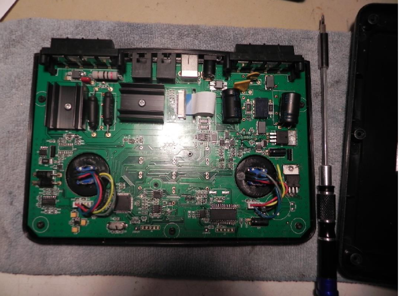
The Elite Motherboard main components:
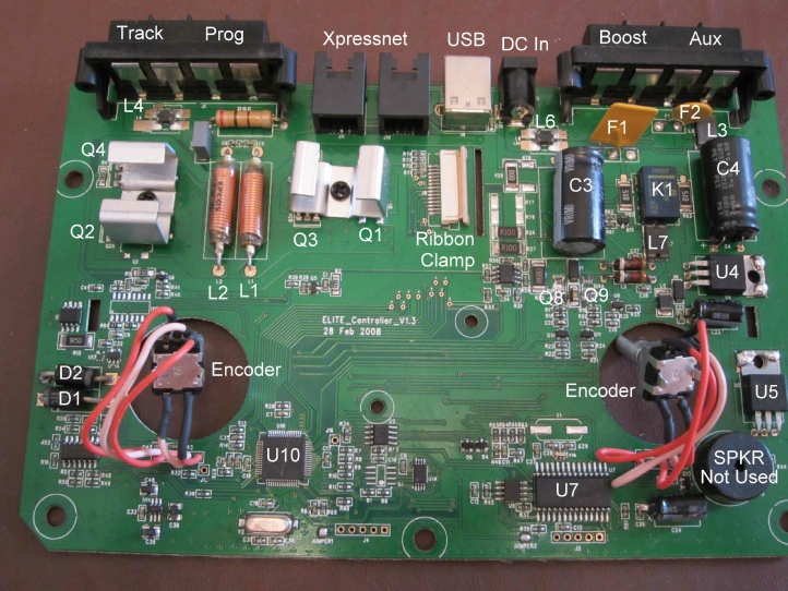
Components:
Code Description Part Number Purpose
D1 and
D2 3 amp Diode 1N5400 Railcom
Encoder 2457-
(Replace with PEC11L-
F1 1 amp 60V Resettable Fuse As marked Aux output
F2 6 amp 30V Resettable Fuse As marked DC input
K1 12V Relay TQ-
L1 and
L2 Inductor As marked or EPCOS Track output
L3 Common mode choke 40R CM3322P400R 4-
L4 Common mode choke 300R CM3032V301R-
or
RS104-
DLW5BTM01SQ21 Track output
L5 Common mode choke 120R 12V Xpressnet
L6 Common mode choke Same as L4 DC input
L7 Common mode choke Same as L3 Prog/Boost output
Q1 and
Q2 Power Mosfet IRFU024N thru’hole Track output
IRFU024NPBF is known to work
Q3 and
Q4 Power Mosfet IRFU9024N thru’hole Track output
IRFU9024NPBF is known to work
Q8 and
Q9 Dual mosfet ZXMC3AM832 s/s by
IRF7509TRBF or RS301-
U4 12V Regulator LM7812CT
U5 5V Regulator LM7805CT
U7 PIC 18F2455 Xpressnet/USB
U10 PIC 18F6527 or 18F6622 Main functions and display
It may be possible to identify other components by referring the board code back to Hornby R&D Dept.
Known faults:
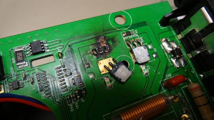
A close inspection of the board may reveal a failed component by way of slight discolouration or there may be a spectacular burn out as is the case below with Q2 & 4, or you may of course use standard fault finding methods to identify a faulty circuit board component.
The following components have been reported as failed by users on the Hornby forums.
Board code L3 (Aux Output) and board code L7 (Prog/Boost Output) are common mode chokes Alternative device not yet sourced.
Board code L4 (Track Drive) is a common mode choke. This is an 8 pin device but the pads are ganged onto 4 pads on the board.
Board code L6 (DC power input) is a common mode choke.
It is acceptable practice to bridge common mode chokes rather than replace them if parts are not available.
Board code Q2 and Q4 (Track output) are an H-
Note the rudimentary bent aluminium heat sinks on these components. Later units have aluminium extrusions like the eLink.
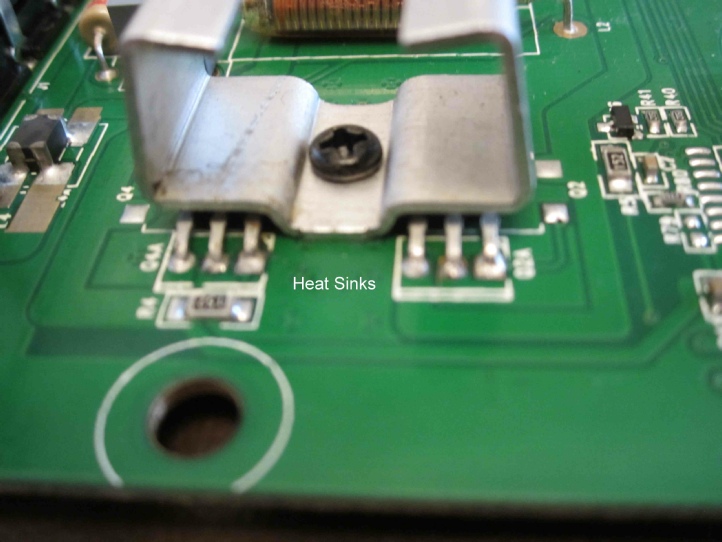
You should remove these heat sinks, clean them up and reapply heat transfer compound to preclude any heat associated failures of the protected components. Ensure the attaching screws are firmly tightened and that the heatsink is flat -
Board code Q1 is same part as Q2 & board code Q3 is same part as Q4 although there are no reported failures to date of these similar components in the same H bridge circuit.
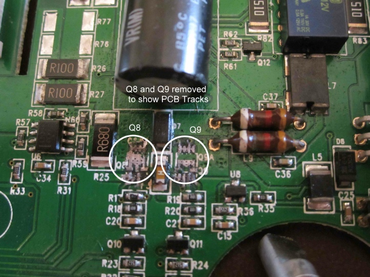
Board codes Q8 & Q9 are 8 pin dual mosfet switching devices, are used in pairs in an H-
These are very small 8-
LCD display screen buffer board code -
The two main integrated circuits are Board Code U10, master logic chip and U7, USB and Xpressnet chip. Even if you were capable of sourcing and installing these components you would need the associated programming code from Hornby to complete the task. This is proprietary information and it is very unlikely Hornby would release that code to any casual user.
Relay K1 (blue box between the large capacitors) is what you hear clicking during programming operations. This flips the DCC low current signal circuit between PROG output and the default BOOST output when actively programming a decoder.
This means if you have an R8239 Booster module controlling a separate power district on your layout this area will drop the DCC signal whenever you are programming.
The rotary encoders are known to be unreliable and Annex A describes their replacement.
The items listed above are the only components known to have failed so far since the Elite controller was introduced in 2007.
In the past Hornby has been very good at providing a part number for items identified using the circuit board designator code. If you can be sure a certain item has failed on your Elite I may be able to provide a part number for that item and even an equivalent part if the original is not easily available from the usual suppliers or we can ask Hornby.
Testing and Upgrading the Firmware:
Functional Test
There is a simple functional test you can do without any other equipment or test gear to check the Elite is in good working order and the screen responds to the buttons.
Power up the Elite whilst holding down the LOCO button. Release as soon as you see Hornby on screen.
The screen will fill with every available character for long enough for you to check them and then hopefully you will see Hornby EE PASS on screen and not EE FAIL.
You can now press each button and see a numerical response on screen – Menu = 01, Loco = 02 plus green led, Acc = 03 plus red led, ... Stop = 09, etc. Pressing and rotating the speed encoder will show 08 then P.20 – P.29 for LH knob, 07 then P.10 to P.19 for RH knob. Number pad buttons will show their own number but as double digits 0 = 00, 1 = 11, etc, 9 = 99.
To recover the Elite just power it down then back up again as per a normal start.
Upgrading Firmware (At the time of writing the latest version is V1.44):
As your Elite starts up it briefly shows the version number of the firmware currently installed. This firmware is user upgradable using a PC with an internet connection and a USB printer cable.
First download and save the latest version of the Elite firmware from the Hornby website. Keep the folder open where you can easily get at the executable application file. In this folder is additional information such as installation instructions and if you need drivers for different versions of Windows on your PC.
You need to connect the Elite to your PC later using a standard printer cable (i.e. with A and B ends).
Tip – do a dry run to find out which COM port Device Manager is allocating to your Elite, by opening Device Manager from your PC Control Panel, then as you plug in the powered up Elite USB cable make a note of which port is allocated as the screen refreshes. Unplug the USB cable and the port will drop out, but use the same port again next time. Power down the Elite and continue as follows.
Power up the Elite whilst holding down the red STOP button. Release after 30 seconds. The Elite is now in Update Mode and you should have a completely blank screen.
Wait a further 30 seconds then plug in the USB cable between the Elite and your PC. This must be a direct connection and not via a USB extender hub.
Wait a further 30 seconds then open the firmware update application file. A dialogue box will appear on screen asking you to choose a COM port. This will be the port number you noted previously if you have used the same USB connection. Select this in the updater dialogue box.
There is second box to select on the new installer and this is PC Type, where you have a choice of 1, 2 or 3. 1 is for old slow PCs, 2 for reasonably fast PCs and 3 is for the very latest PCs. If in doubt choose Type 2.
Click OK and the dialogue should change to a downloading progress bar.
If you have matched your PC to the correct Type then after 3-
If you have chosen the wrong PC Type, too low and you will see very slow progress which can take up to an hour to complete, but is usually successful nonetheless, or if you have chosen too high the progress bar will zip through in less than 2 minutes and you will see Fail.
If the latter happens the Elite will become unresponsive and will not reboot at all – effectively broken, so just unplug the power and USB and set it all up again from square one carefully observing the delays between actions, then pick a slower (lower number) Type and try again.
If you had the long wait then next time you know you can choose a higher PC Type.
Tip – stick a label on the back of your Elite with the PC Type and COM port numbers for next time.
The latest firmware update installer has proven totally reliable on all types of PC from XP to Win 10 and processors up to and including Intel i7, however if it does fail then it probably means you have rushed a step, so just unplug and go back to square 1 again.
Acknowledgments:
Many thanks to Ken Wards of Hornby Research and Development Department for his help in providing part numbers for the circuit board codes quoted in this article and to Ed Cairns for finding replacements for the encoders and writing up their replacement.
RH/Elite-
Annex A -
By Ed Cairns
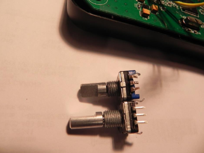
The rotary encoders used were PN PEC11L-
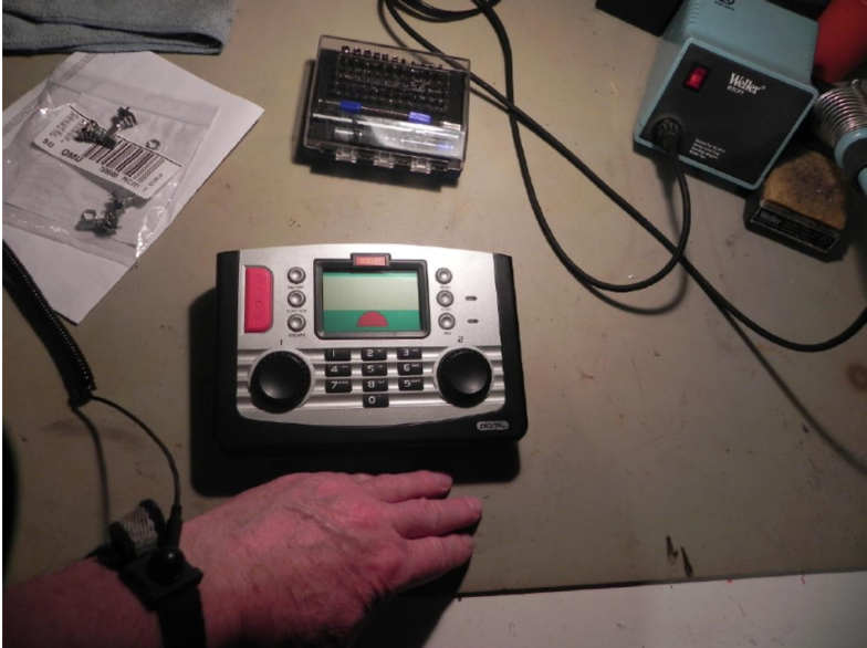
My Elite controller had started to develop bad jitter from the controller knobs -
I went to work on the Elite using an anti-
Figure 1 -
The next step was to open the controller case (reference Teardown instructions earlier).
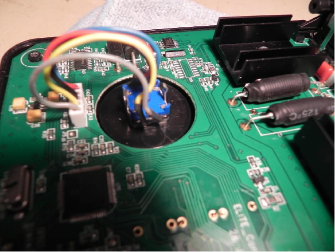
Figure 2 -
I cut the leads on only one encoder at a time, leaving the other for reference. I then slid the original black heat-
Figure 3 -
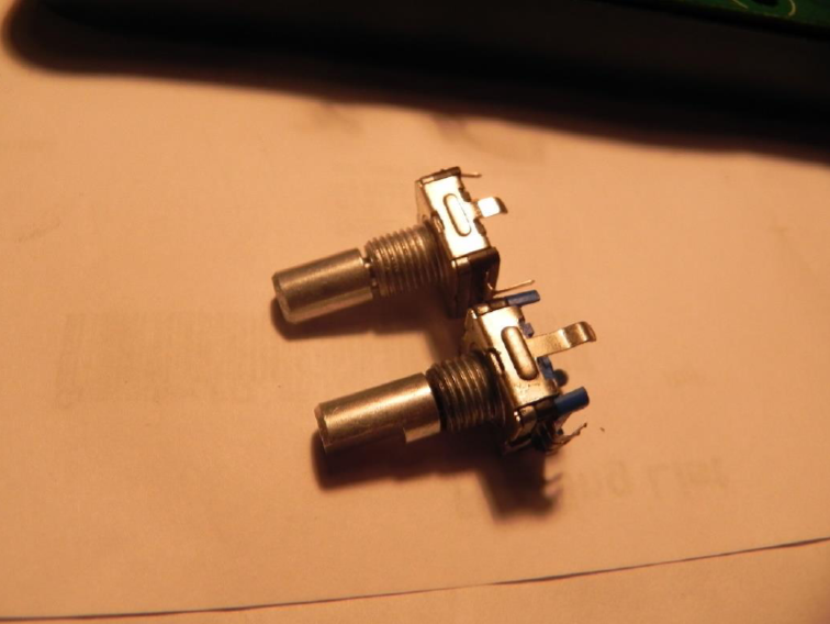
The encoder used here is PN PEC11L-
A better match is PEC11L-
Figure 4 -
However with a small hacksaw, file and bench vise -
Figure 5 -
Once the shafts were shorted to length it was on to soldering -
Figure 6 -
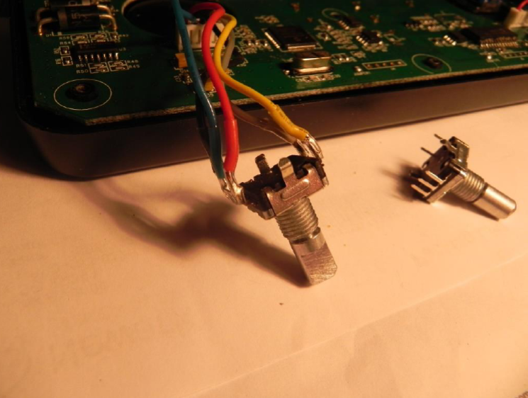
I then repeated the process for the remaining encoder and reinstalled the encoders in the chassis.
Figure 7 -
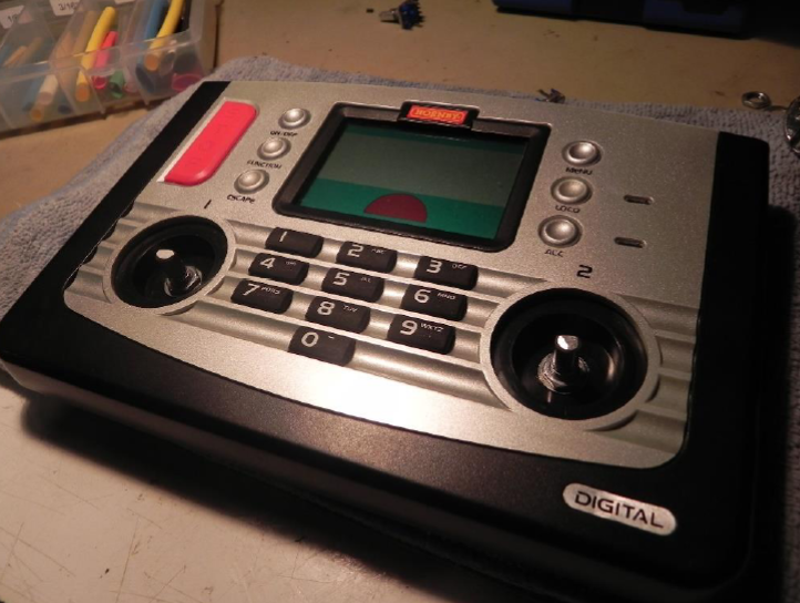
Due to the longer threaded part I think the knob height may be very slightly higher -
Figure 8 -
Then on to Testing…
The detents are more pronounced but I don’t think that is unacceptably so.
The address doesn’t jump when pressing the knob to select it.
The control for locomotive speed was smooth and did not jump or jitter -
So for $3.50 Canadian, it seems like a reasonable solution to worn Elite control encoders and it saves the need to purchase a new Elite controller.
Figure 9 -
Ed Cairns -
ROB’S RAILS -
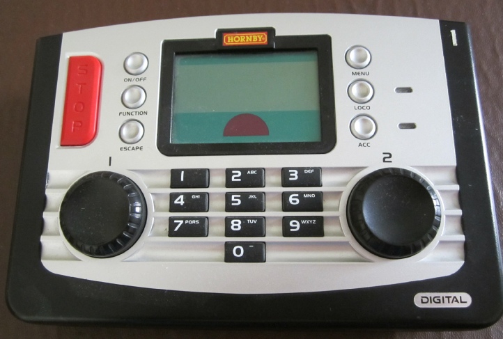
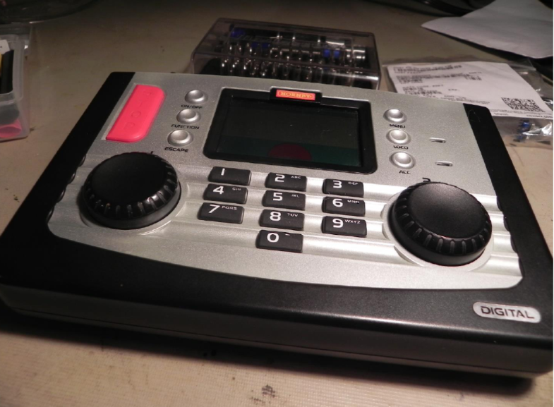
Hornby R8214 Elite DCC Controller
This report details the procedural teardown of a Hornby Elite DCC Controller, highlights any parts that are known to have gone faulty, tells of their physical circuit board code, identifies their original part number and where applicable provides an equivalent part by supplier code.
The report has been amended to include Annex A which is a write up by Ed Cairns of Calgary in Canada describing how he sourced suitable encoders and replaced them on his Elite. My thanks to Ed for his input.
© Rob’s Rails 2019 -