The procedure totally dismantles the unit, but you only need to dismantle as much as is necessary to access those parts you wish to work on.
This information is provided in good faith, but as I have no idea of your skill levels it is assumed you know what you are doing and that you work on your Select at your own risk.
Be aware that opening the case and/or making changes or attempting repairs to this unit will invalidate any warranty on your Select and may also preclude any future chance of Hornby being able to repair or even update the unit. This also applies to any Select bought second hand, whether working or not, as the previous owner may have opened the case or attempted repairs.
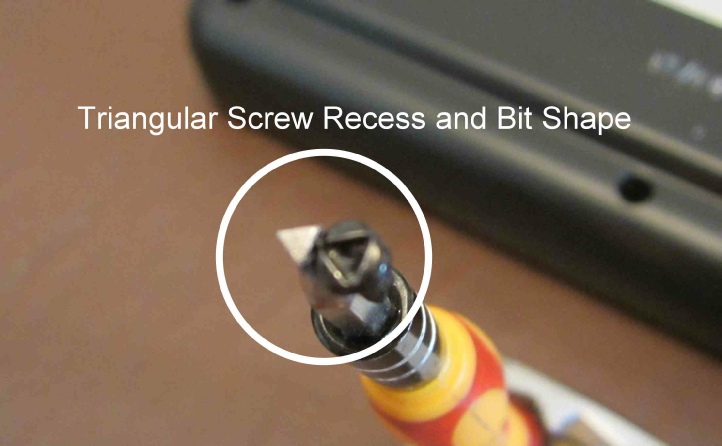
The lower case is attached with qty x 9 triangular recess screws, for which you need a special bit.
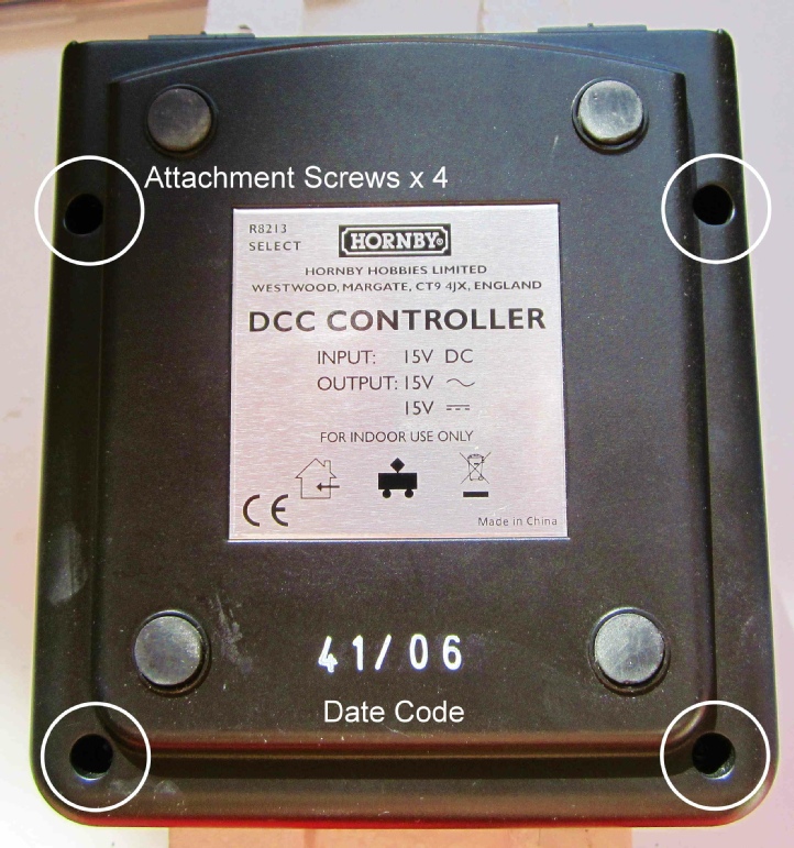
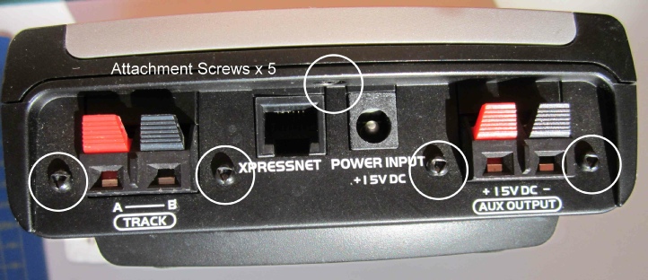
There are qty x 4 screws in the underside, qty x 4 in the back panel and qty x 1 up into the top panel from the back panel.
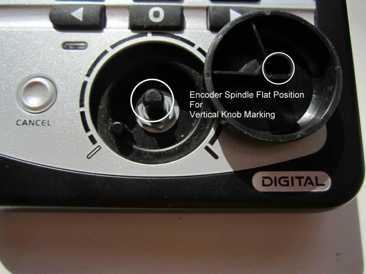
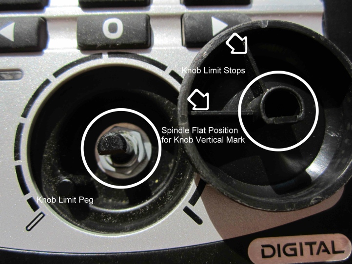
The speed encoder knob pulls off but may need to be prized up with a thin blade to get it started. Position the knob with the marker vertical before removing as the knob has limit stops moulded in which butt against a peg in the case. Note the position of the flat on the encoder spindle for reassembly. This will ensure the knob is replaced correctly later.
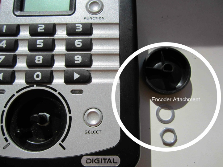
Remove the nut and washer from the encoder spindle and rotate the lower case away from the top case.
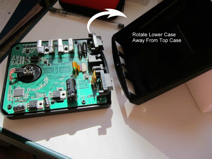
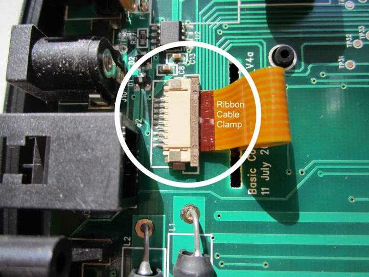
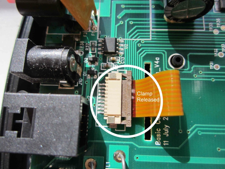
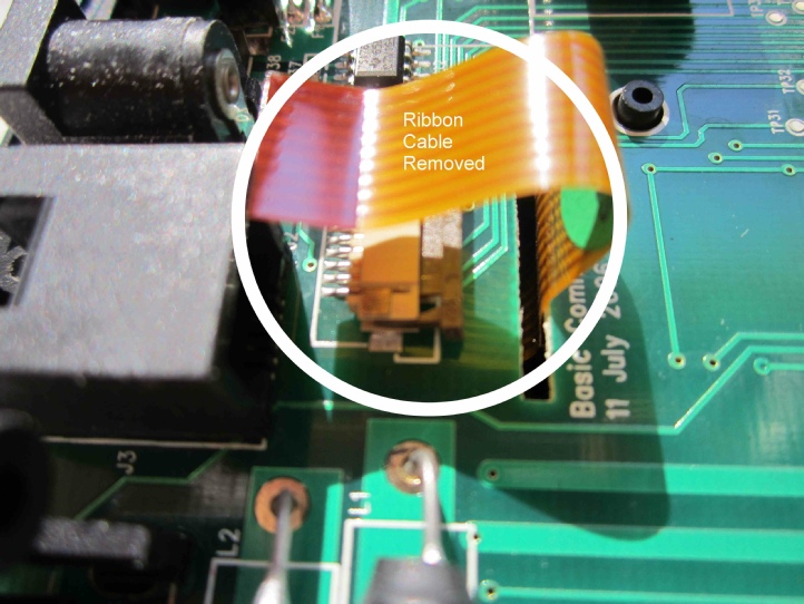
Release the beige locking bar on the ribbon cable clamp and ease out the ribbon cable.
Release the qty x 2 clips securing the motherboard and the board will lift clear taking care to allow the ribbon cable to feed out of the slot.
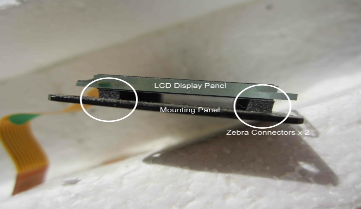
The LCD screen is held in place by qty x 4 cross point screws.
It can then be carefully lifted clear. Note the elastomeric (zebra) connectors. If you have had corruption of the screen characters then you can carefully ease the screen away from the daughter board and clean with isopropyl alcohol (IPA), allowing all parts to thoroughly dry before reassembly. The design of zebra connectors means alignment is not critical to satisfactory performance but try to match the original positioning as far as possible.
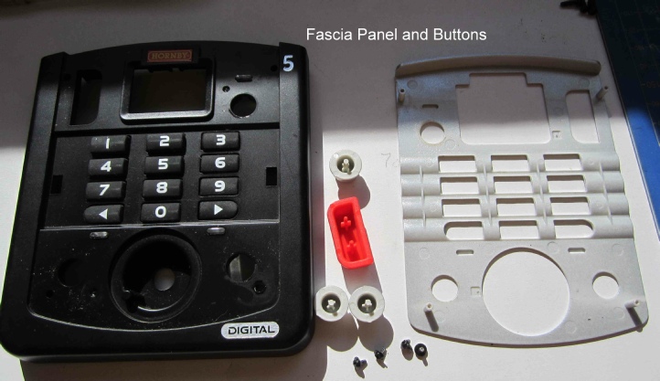
The top case facia is held in place by qty x 4 cross point screws, but nothing is gained by its removal unless you want to give it a good clean.
The buttons just lift out if required.
Reassembly is the reverse of dismantling except care must be taken to thread the ribbon cable through the motherboard slot before you click the board into place, then fully seat the ribbon cable into the clamp as you press the beige locking bar into place.
Also after securing the encoder with the nut and washer turn the spindle until the flat is positioned as noted earlier and press the knob back into place. The mark on the knob should be vertical. Check for full range of travel left and right up to the marked limits.
At this stage you should power up the Select using either the DC power supply or an Xpressnet cable from an Elite controller and check all the buttons work. Avoid touching any part of the motherboard whilst carrying out this check. If all is well power the Select down and refit the lower case.
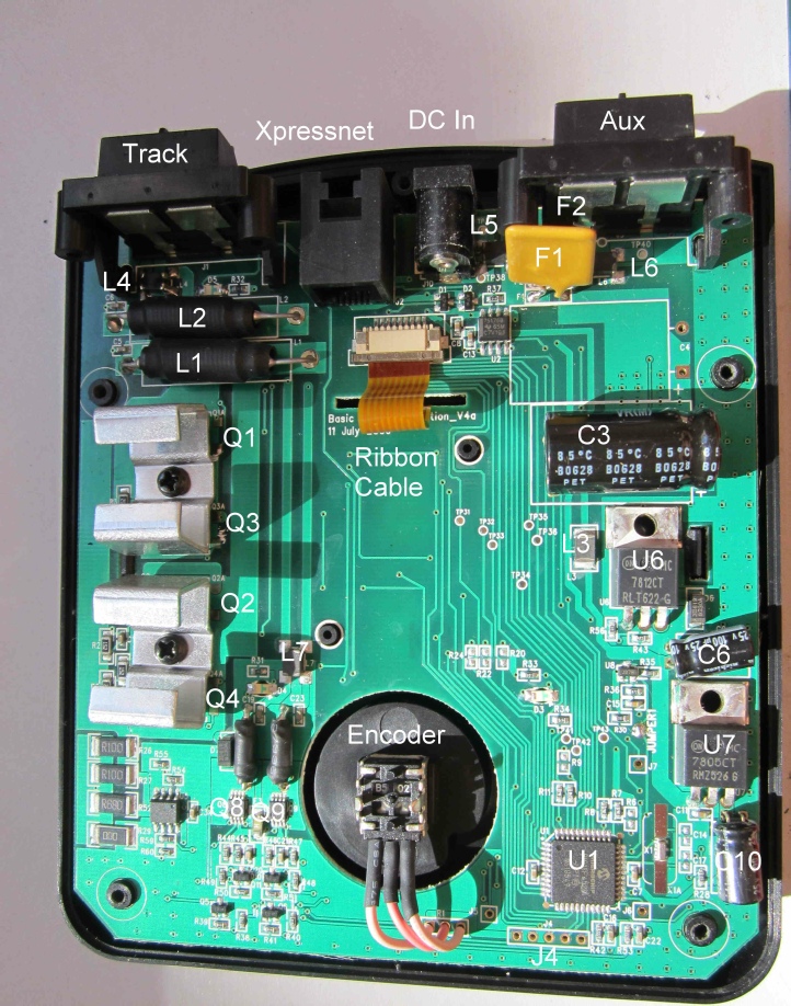
Select components:
Major components are shown in the picture below and listed in the table following. At the time of writing no major failures have been reported but the table identifies these items for reference.
Components:
Board Code Description Part Number Purpose
C3 Capacitor As marked 15V to track
C6 Capacitor As marked Track output
C10 Capacitor 100μF 25V 5V regulated
F1 3-
F2 0.9-
L1 Inductor 7μθ Track output
L2 Inductor 7μθ Track output
L4 Common Mode Choke CM1812R 600R-
L5 Common Mode Choke CM1812R 600R-
L6 Common Mode Choke CM1812R 600R-
L7 Common Mode Choke CM1812R 600R-
U1 PIC 18F4520 Main functions and display
U6 12V Regulator LM7812CT DC input
U7 5V Regulator LM7805CT 5V regulated
Q1 Dual mosfet IRLU024NPBF Track output
Q2 Dual mosfet IRLU024NPBF Track output
Q3 Dual mosfet IRF9024N Track output
Q4 Dual mosfet IRF9024N Track output
Q8 Dual mosfet IRF7509 Boost output (Xpressnet)
Q9 Dual mosfet IRF7509 Boost output (Xpressnet)
XX Display Screen TRI-
Known faults:
Although limited in capability of loco and accessory decoder address ranges and not being able to change configuration variable (CV) values other than addressing, acceleration and deceleration the Select is a very reliable unit and there have been no reported faults with it apart from ringing of the DCC signal which can be resolved by loading the track with locos, even if they are not moving.
Speed control knob operation can become rough due to debris under the knob. Easily fixed by removing the knob and cleaning the recess.
Firmware Update:
At startup the Select screen reports three pairs of numbers (1x -
10, 11, 12, 13, 14 or 15 which is the firmware revision state (v1.0, v1.1, etc to v1.5).
Then 30 which is the motherboard version standard.
Then 03 which is the default loco address, indicating the unit is ready to operate.
The firmware can only be updated by return to works at Hornby. To arrange this to happen contact Hornby Customer Care by phone (see Hornby website for the current number) for a job ticket number. There is a modest charge for this of £15 at time of writing which includes return postage and packing.
The latest version is v1.6 which has improved overload protection and allows you to change allowable values for all CVs 1-
Acknowledgments:
Many thanks to Ken Wards in the Hornby Research and Development Department for his help in providing part numbers for the circuit board codes quoted in this article.
RH/Select/May2019/v1.2
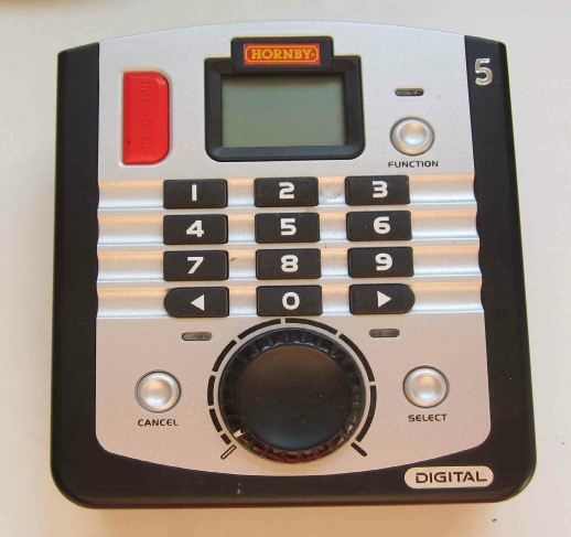
ROB’S RAILS -
Hornby R8213 Select DCC Controller
This report details the procedural teardown of a Hornby Select DCC Controller, highlights any parts that are known to have gone faulty, tells of their physical circuit board code, identifies their original part number and where applicable provides an equivalent part by supplier code.
© Rob’s Rails 2019