Converting the Hornby Blue Rapier to DCC and modification of the directional lighting.

Parts Required:
2 x 8-
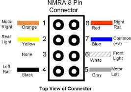
Note: This conversion does not use Pin #3 (green wire).
2 x 3mm -
2 x 3mm -
Note: Only positive anode 3-
2 x Hornby R8249 basic decoders or similar decoders of your choice.
Sundries -
Note: There is no need for additional resistors as each PCB has an on-
Preparation:
Unclip the overhead power rail from the power and trailer cars’ corridor end cap and very carefully unclip the end cap at each side. Each cap is secured by 4 hooks engaging into a recess on each side of the main body. These are easily broken and replacement end caps are hard to find.
Unclip the chassis from the body by springing the body sides apart and removing the rear of the chassis down and out whilst pivoting about the front (pointy) end.
For the purposes of the conversion left and right are as marked on the printed circuit boards (PCB) at the pointy end of each car. Directional lighting wiring logic may seem to be wrong as a result but remember the trailer car is sitting pointy end facing backwards, hence the white and yellow wires logic is reversed in this car. Follow the instructions as presented and your directional lights will work correctly at both ends in both directions.
We will start with the trailer car as this is the simpler of the two cars to convert.
Trailer Car Conversion:
Unsolder and tag for identity both pickup wires from the PCB -
Note: This is contra to obvious logic but as the trailer car runs pointy end to the rear going forwards TL is picking up from the right rail and TR from the left rail in direction of travel.
Solder these wires onto the decoder socket as follows:
Note: If necessary extend these and any other wires using a matching wire colour to aid any fault finding in the future.
Connect the Ex-
Connect the Ex-
Note: It is possible to replace the existing LED without removing the PCB from the chassis, but the task is easier if you do.
Remove the screw securing the PCB to the chassis and lift the PCB clear. Retain the screw for later.
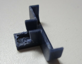
Carefully remove the blue Tee shaped plastic part covering the LED by prising from the edge using a modelling knife. There are 2 x pegs which locate into the PCB. Place this part to one side for now.
Unsolder the existing LED from the PCB. This is no longer required and may be discarded.
Identify which leg of the new 3mm red/white bi-
The longest leg (middle) is positive.
The shortest leg is white.
The intermediate length leg is red.
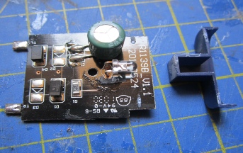
Referring to the picture below -
Now bend the red leg to shape, as shown below, to avoid other components on the PCB and the screw.

Mount the new LED to the PCB with the LED resting on the board, the positive leg in the hole marked + and the white leg in the other hole.
Note: If attempting to do this without removing the PCB then crop the downward facing legs first.
Solder the positive and white legs to the PCB, then trim the legs to length on the underside.
Run a new white wire from the LED red leg (use heat shrink tube as insulation against shorts to the PCB) to the decoder socket white pin #6. This wire switches the trailer car red lights on when the train is travelling forwards.
Run a new yellow wire from the PCB TL connection to decoder socket yellow pin #2.
Run a new blue wire from the PCB TR connection to decoder socket blue pin #7.
Make up 2 x posts from plastic sprue, glue to the chassis in a suitable place to use as mounts for the decoder socket. Pilot drill the posts and mount the socket using the 2 x small self tapping screws as below.
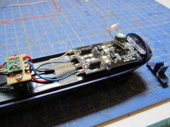
Note the PCB shown above is from the power car and before the bi-
If you wish to install a Hi-
Reassemble the PCB to the chassis and secure with the screw from earlier. If you bent the new LED legs correctly the nose of the lens will just touch the clear plastic light bar.
Install a decoder making sure the orange pin on the plug matches pin #1 on the socket, else the lights will not work at all. Check the lights work in both directions and the logic is correct, i.e. white lights show when loco is selected reverse and red lights show when loco is selected forwards. At this stage do not give the decoder its final address as we will do that later.
Trim the Tee shaped blue plastic cover as necessary to fit over the new LEDs and wiring and glue back into place on the PCB, sealing with blak-
Attach the decoder to the chassis using double sided tape or pad.
Refit the body to the chassis and clip the corridor end cap into place. Recheck the lights still work and that the Cyclops light aligns with its housing in the body. If you have damaged the end cap hooks then you may have to glue the end cap on but not before you are sure everything works OK.
Note: The decoder green wire is not used in this conversion. It could be used to power coach interior lighting but as this model has dark tinted windows and no internal detail there is little point.
Power Car Conversion:
This is essentially the same procedure as for the trailer car except the PCB has 4 sets of wires -
With the body removed as before.
Unsolder and tag for identification the existing wires from the PCB. Make sure you keep pickup wires from each side tagged together respectively.
Note: Viewed from left to right (facing in normal direction of travel) we have:
TL 2 x wires from the front and rear bogies left side pickups.
M-
M+ 1 x wire from motor right brush connection.
Note: Motor brush connections are clearly visible on top of the motor and should not be confused with the bogie pickup connections visible on the side of the motor. This is not helped by factory wiring being all being black.
TR 2 x wires from front and rear bogies right side pickups.
Remove the PCB and blue plastic cover as before.
Replace the existing LED with the new bi-
Install the Cyclops Led exactly as before.
Reinstall the PCB to the chassis and wire up as follows:
Solder the Ex-
Solder the Ex-
Solder the Ex-
Solder the Ex-
Run a new white wire from the PCB TL connection to the decoder socket white pin #6.
Run a new blue wire from the PCB TR connection to the decoder socket blue pin #7.
Run a new yellow wire from the bi-
Make up mounts for the decoder socket from plastic sprue as before, glue to the chassis, pilot drill and install the socket using 2 x small self tapping screws.
Install a decoder and check the lights work and in the correct logic, i.e. white lights showing when loco selected forwards and red lights showing when selected reverse. Compare with trailer car to ensure when power car is white trailer car is red and vice versa.
Trim and install the Tee shaped blue plastic cover as before.
Refit the body and corridor end cap.
Addressing the decoders:
Place both the power car and the trailer car on your programming track and assign them the same address of your choice.
Operation:
Both decoders will correspond to the same address.
Switch on directional lighting using F0 from your controller functions.
When the locomotive is selected forwards the power car will show white lights and the trailer car will show red lights.
When the locomotive is selected reverse the trailer car will show white lights and the power car red lights.
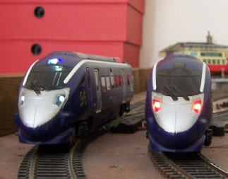
Note: In this picture you can plainly see what happens if the Cyclops light LED is not positioned correctly.
Rob Honnor. May 2017 v1.0.1 Blue Rapier DCC and Lights.
Hornby R 1139 Blue Rapier Class 395
This article details conversion of the Hornby R 1139 Blue Rapier train set Class 395 electric locomotive power and trailer cars to DCC and to improve the existing limited directional lighting.
The conversion incorporates an 8-
The model has dark tinted windows which preclude being able to see any interior detail, which is not installed anyhow, thus the provision of interior lighting is not attempted.
ROB’S RAILS 
Article 9 -
© Rob’s Rails 2018