Converting the Hornby Mallard to Twin Track Sound and a Fixed Drawbar.
Parts Required:
X6211 -
X6113 -
X9958 -
X9333 -
X-
Spares can easily be obtained from Hornby Spares Shop, Peter’s Spares, New Railway Modellers Shop, and other suppliers.
Reference:
Hornby A4 Service Sheets listed in the introduction.
Method:
Note: -
1 Disconnect tender from loco by lifting the tender post from the powered drawbar.
2. Support loco body inverted in a suitable cradle. I made mine from a few pieces of polystyrene foam glued into a U-
3. Remove the shouldered screw securing the drawbar to the fixed pony truck block -
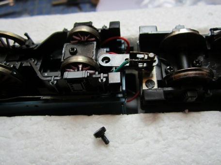
4. Remove loco body by removing the single shouldered screw under the front bogie -
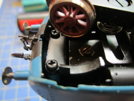
5. Remove the tender body by first removing the rear fishtail coupling and then removing the screw concealed beneath -
6. Unsolder the speaker wires from the TTS speaker and set the speaker and enclosure aside for later.
7. Cover the decoder with a piece of heat shrink tube and plug the TTS decoder into the 8-
8. Screw the new drawbar back onto the loco chassis using the old shouldered screw -
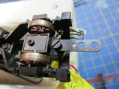
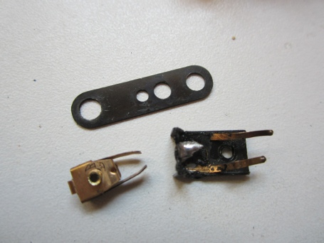
If you do not have a new X6211 drawbar to hand then carefully drill out the brass rivet holding the electrical contacts to the old drawbar and use that metal ink -
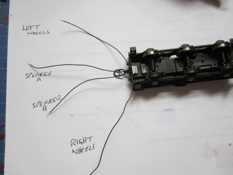
9. Take the X6113 plug and tag the wires per the picture The 6-
10. Solder the wires from the old drawbar to the 4-
11. Route the 4-
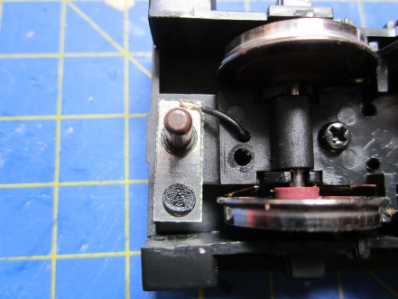
12. Modifying the tender. I removed the old tender post and replaced it with a bolt as shown in some of the illustrations, but in hindsight it would have been just as easy to leave it in situ so I will describe the conversion as if the post is left in situ. Unsolder the 2 pickup wires from the tender post -
13. Remove the weight from the tender chassis by removing the 2 small countersunk screws, set aside for later.
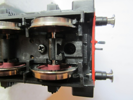
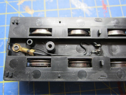
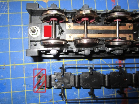
14. Invert the tender chassis and remove the 2 screws securing the tender bottom which secures the wheels. Modify the tender bottom by cutting off as shown hatched in the illustration and also make a rectangular hole shown red in the chassis to accept the X9958 4-
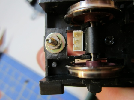
15. Solder the existing pickup wires to the outer contacts of the 4-
16. Solder 2 wires to the inner pair of contacts long enough to reach the speaker.
17. Secure the socket into the well in the tender chassis with glue and pack above it with plastic card or wood shims -
Note: -
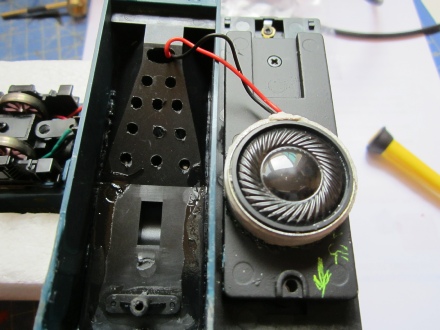
18. Refit the chassis weight and run the speaker wires as shown above via the front to the speaker. The speaker is mounted face up in an enclosure made from an old plastic Humbrol paint ‘tin’ cut down to suit. The enclosure tube is trimmed so that the speaker will clear the coal chute inside the tender body. Secure the enclosure to the chassis weight as shown with glue and fix the speaker into the enclosure using blu/white-
Note: -
19. For the face up speaker installation only, drill 3mm diameter holes in the coal chute and 1mm diameter holes in the dummy coal load to allow sound to escape. Face down speakers allow sound to escape through holes in the chassis.
20. Invert the loco and tender and attach the 4-
21. The loco and tender bodies can now be refitted and Mallard returned to service.
RH/Feb-
ROB’S RAILS 
Article 7 -
Hornby R2339 -
This article is about improving Hornby’s DCC Ready Mallard by replacing the unreliable spring finger and clamp power transfer drawbar with a fixed drawbar and a 4-
Hornby ‘s Twin Track Sound (TTS) is also installed in the tender. At the time of the conversion a Class A4 3-
Reference should be made to Hornby Service Sheets numbers 256, 275, 350, 358 and 394 as applicable to your model and for new replacement parts.
© Rob’s Rails 2015