Hornby Class 90 – R062, with 3-
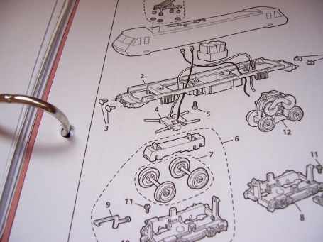
Referring to Hornby Service Sheets SS146 (early Class 90) and SS209 (later Class 90):
The front and rear bogies simply unclip from the chassis and all wires are disconnected (front bogie shown).
The motor itself also unclips from the motor bogie frame – take care to note the orientation of the motor with respect to the frame.
Motor Improvement:
Although the motor ran smoothly on the rolling road, it was very short on power on the track, hardly being able to pull its own weight so it was decided to give it a general service and replace the magnet with a neodymium one.
The magnet was sourced from Bowlerscroft via eBay. There are many different neo-
The motor was also given a general service by replacing the brushes and springs and gear-
Once rebuilt lubricate sparingly then temporarily attach wires to the motor terminals and check for smooth reliable running.
Front bogie modification:
Referring to Hornby Service Sheet 209 for the later Class 90 3-
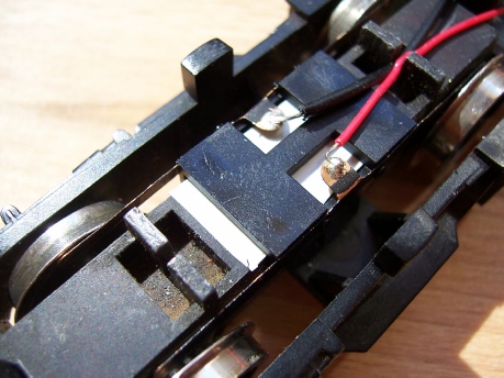
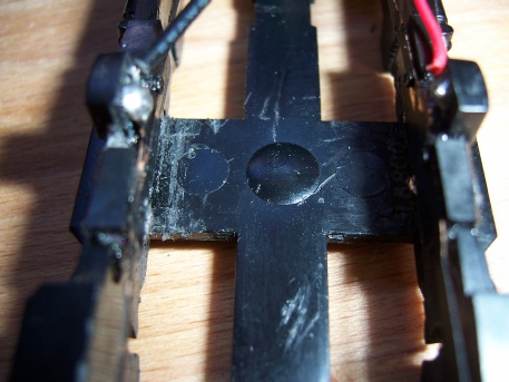
As a precaution against any chance of shorting, I put a piece of (white) insulating tape on the metal front bogie beam – see photo.
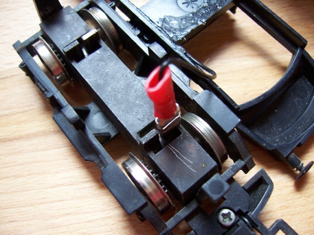
Take care when clipping the collector in place to avoid damaging the wheel wipers by holding them inwards and pressing the collector bridge in place one end at a time. The red wire should be on the right to accord with wiring convention. Once centralised secure the bridge piece with a drop of super glue.
Check that the wipers are rubbing correctly on the wheels and are not displaced by the gears like the one directly above. You can if you wish file down the gears to give you more room for the wipers but check that they are rubbing on metal and not plastic. I didn’t bother as the wipers ran true on the wheel inner rim.
After cleaning the wheels, this bogie can be clipped back into the locomotive chassis taking care not to trap either of the wires. Note that we now have 2 wires instead of the single wire on the original configuration. Leave these for now until we get around to the wiring up stage.
Motor bogie modification:
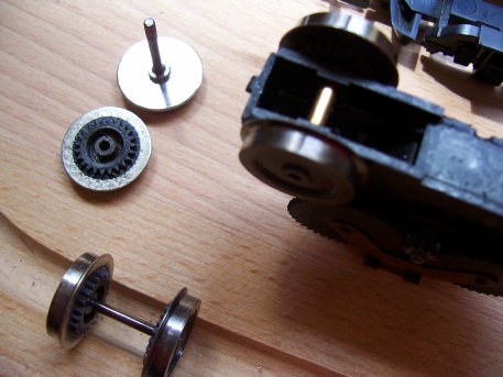
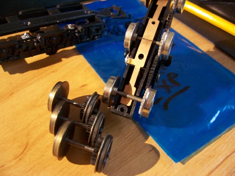
We will use a front bogie wheel set with solid wheels to replace the traction tyre’d motor bogie wheel set.
I used item 7 (see SS209 parts list above), part number X8789 from the later model, but just be aware that there is a slight difference between these and the original wheels (X1445 on SS146).
The original wheel set is live from the axle to the left side wheels, which is how the beam collects current from the track. These front wheels also have gears on the right side wheels and it is these gears and current collecting properties we need to help improve the motor bogie.
The old style front bogie wheel set can be used on the motor bogie, but the later front bogie wheel set has gears on both sides and both wheels are insulated from the axle.
If using the older model front bogie wheels with their live axle we need to be aware that the motor chassis is also made live and that we only need to fit a single pickup set to collect from the gear side wheels. With the later model wheels with the dead axle we need to fit new pickups on both sides.
The old traction tyre’d wheels are carefully prised apart (I used long nosed pliers as a wedge), removed from the motor frame, then replaced by the new solid wheels taking care to check the back to back measurement is correct using a gauge.
Note that if you are fitting the older front bogie wheels then the non geared (right hand side) wheel will be live and you can collect this current from the wire that was attached to the motor frame as before. If you are using the newer insulated axle wheels then this motor frame wire is not used.
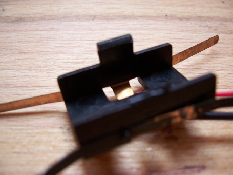
To install new pickups to the motor bogie we take our spare collector assembly X8786, cut it in half along the centre line and trim the resulting flanges to fit our motor bogie frame – rather than write a thousand words to fully describe this chopping around please see photos.
This shows one flange clip removed prior to cutting in half lengthwise along the centre line base of the U channel.
The bogie frame may also need a trim of the reinforcing triangles in the floor to clear our new pickup units. I took them out completely before I realised I could get away with gentle trimming.
Glue these new collectors in place as shown (single or double according to your plan) making sure you have the red pickup wires to right hand side and black wires to the left to accord with wiring convention. If you are only using one pickup then it should be on the motor gear side and should be black.
Carefully adjust the pickup wipers so that they will rub evenly across the outer face of the motor bogie wheels, and clip the motor unit back into the bogie frame taking care not to distort the wipers.
Clip the motor bogie back into the locomotive chassis. Check for full and free rotational movement.
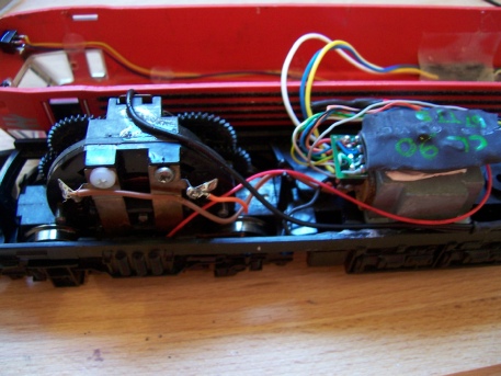
Wiring up:
This is simply a case of joining the red wires from the front and back bogies to each other and then to the decoder socket red wire and do the same with the black wires. If you are only using one pickup with the older wheels then reconnect your red wire to the red wire from the decoder socket, crimp on a ring terminal and connect to the motor frame with the screw from earlier. Carry on as above with th eblack wires.
Reconnect the motor wires from the decoder socket to the same terminals as they were previously -
If you have retained the live pantograph switch and have not converted to DCC, then join the black wires from front and motor bogies together then to the pantograph switch and from the switch to the motor as before -
Completion:
Check the locomotive runs well on a rolling road if available or if not place the body on loosely and test run on track, then if OK fully fit the body and recheck running.
Rob Honnor -
Class 90 Improvements
This article is about improving the running of this early electric locomotive by modifying the Ringfield motor and adding additional pickups to the front dummy bogie and rear motor bogie using standard parts from a later locomotive.
Preparation involves removing the locomotive body by releasing a clip at each corner from a matching slot in the body and lifting the body up and away, taking care to disconnect the wires attached to the live pantograph slide switch that is only useful on DC tracks.
You can by-
ROB’S RAILS 
Article 6 -
© Rob’s Rails 2015