Notes:
I) The following method is specific to the coaches in the title, but applies in general to many other marques of coach. Opening up other coaches may require different procedures. Check with the service sheet if available. Be careful of dislodging fragile detail parts when opening coaches.
II) Hornby supplies these particular coaches with metal wheels with one wheel electrically insulated from the axle and the other wheel live to the axle. Similar wheel sets are available as spares under code X9096 for lighted Pullman coaches if your particular coach does not have them.
III) By selecting which side the live wheel is on you can arrange to have each axle of a single bogie opposing or matching its companion axle.
Bogie axles on a single bogie opposing i.e. front axles on both bogies live to a left rail pickup and rear axles on both bogies live to a right rail pickup. For the purpose of this project front means in the normal direction of travel.
Both axles on individual bogies matching i.e. both axles on the front bogie connect to a left rail pickup and both axles on the rear bogie connect to a right rail pickup. Again front is in the normal direction of travel.
IV) Hornby has made it easy to mount axle wiper pickups on these bogies, as there are several cross members to mount to and retain the pickups without having to drill holes, just use a dab of glue.
V) For this project I have recycled the phosphor bronze fingers from redundant Hornby R602 track power clips. R8242 DCC clips are also suitable but strangely more expensive for less piece parts (no capacitor). For the opposing axle version I use the short fingers and for the matching axle version I use the long fingers. Simple to install commercial coiled spring axle wiper pickups are available to purchase if you do not want to use your own e.g. from DCC Concepts.
VI) The described installation is for running under Digital Command Control (DCC) with the lights on all the time.
VII) To have the lights switchable under DCC you will have to install a suitable decoder between the pickups and the lights. There is room in the toilet compartment to hide a decoder from sight behind the frosted window.
VIII) For operation on DC a bridge rectifier will be required in the circuit to ensure the lights work in both travel directions. Again this could be hidden in the toilet compartment.
IX) Details of how to convert the lighting for scenarios VII) or VIII) is not covered by this article.
Method:
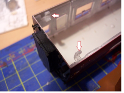
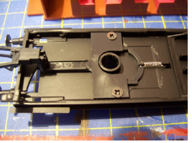
Unclip the body from the chassis by carefully prying inwards the 4 clear plastic lugs (one at each corner of the chassis with a flat screwdriver (Photo 1 -
Photo 1 Photo 2
The lighting described is modified IKEA Ledberg Type L0911 units. 3 x clip together light bars are supplied with a 12V DC output, mains-
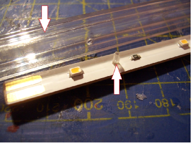
Remove the IKEA LED board board from its plastic housing by pushing in the small clear plastic peg, near the socket end using a small diameter probe. Slide the board out from the plug end and discard the housing and peg (Photo 3 -
Photo 3
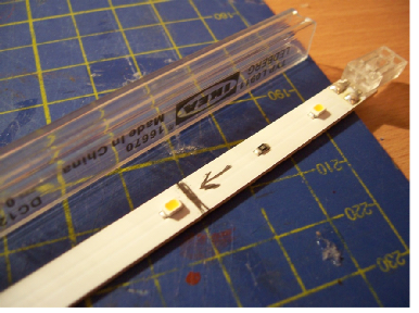
Measure the LED board against the coach seating insert and trim to length with a fine saw or knife at the springy plug end as shown (Photo 4), leaving approximately 3-
Photo 4 (typical but not actual trim point for this model)
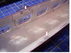
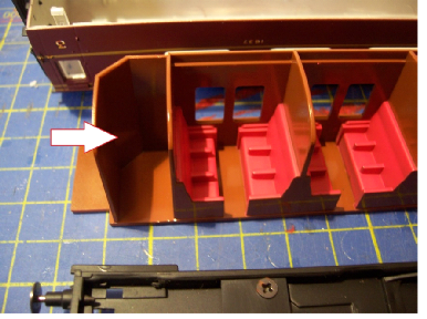
In this model the seating insert partitions fit right up against the coach body roof, so we need a recess for the LED board, using it as a guide to mark up then notch the seating insert to accept the board (Photo 5 -
Photo 5 – typical notching but not actual model, wires not shown
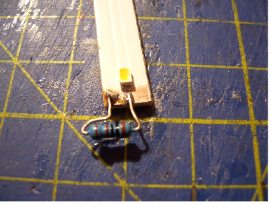
Solder 30 mm long thin flexible wire leads to the copper pads at the socket end of the LED board (Photo 5 -
Note: When it comes to soldering these leads it may be easier to work backwards by soldering the feed wires to the pickups first then feeding them back through the bogies to the light bar before fixing this in place.
Photo 6
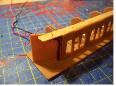
Drill a hole for the feed wire leads in the coach seating insert directly above a small recess in the chassis beside the chassis weight on the corridor side. Continue to drill through the chassis recess at an angle toavoid damaging any under-
Photo 7a – single wire shown, led board not shown
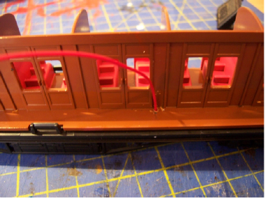
Paint the leads to disguise them if desired and as the seats are nicely painted you may wish to seat some passengers (Photo 7b -
Photo 7b – ready for passengers
At this stage you can loosely assemble the body and seating insert and temporarily connect the IKEA power supply to the feed wires to asses overall brightness. If too bright install a further fixed value or miniature variable resistor in one of the feed wires until satisfied. If too white then a dab of yellow paint on each LED will tone them down.
There is no need to remove the bogies on this model to install the pickups, but you may find it easier to work the next stages if you do and it also gives opportunity for maintenance and/or lubrication of the sprung coupling mechanism.
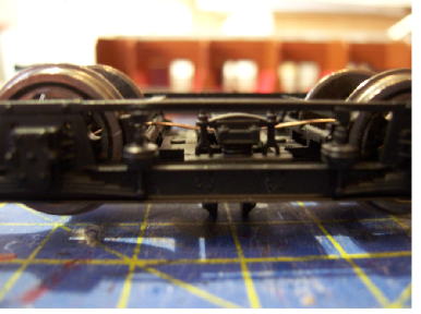
Photo 8 – underside view
Remove one or both bogies from the chassis according to the type of installation you intend -
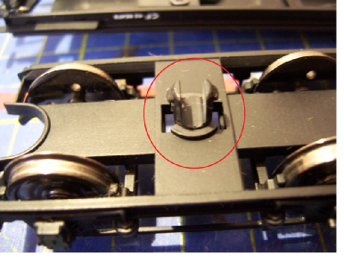
Photo 9 – bogie pivot pin
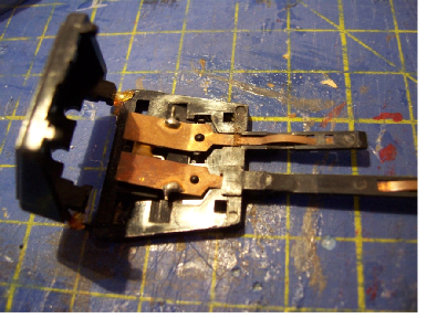
For this project I reused some redundant Hornby track power clips as a source of phosphor bronze for my pickups (Photo 10). Pry open the case and pull out the metal strips with pliers. Unsolder and discard any capacitor.
Photo 10
There are 2 separate pickup arrangement options described:
First opposing axles on either or both bogies using the short strips.
Secondly matching axles on opposing bogies using the long strips.
You will obviously not use both options together on one coach.
Single or Both Bogies -
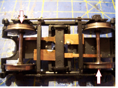
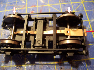
Check with a continuity meter that each axle on each bogie has its live wheel side opposing the other axle e.g. front axle has live wheel to the left and rear axle has its live wheel to the right (Photo 11 -
Making use of the various existing plastic parts on the bogie frame thread one short pickup strip through to bear on the front axle and the other strip to bear on the rear axle (Photo 11).
Photo 11 – underside view -
Adjust the pickups for best electrical performance without inducing excessive friction. Click the bogie back into the chassis. Solder one of your feed wires through the chassis and bogie to each strip. Where possible solder the feed wires to the strips before installing to preclude any chance of melting plastic parts. This could mean working backwards from the bogies up to the LED board as mentioned earlier. If using both bogies extend the pickup feed wires to the other bogie, ensuring the left feeds and the right feeds match bogie to bogie, else a short circuit will be present. Ensure the bogies have full and free range of movement without straining the feed wires. Attach wires with a dab of glue and paint to disguise if required.
Both Bogies -
Check with a continuity meter that both axles on the front bogie have their live wheels to the same side and that both axles on the rear bogie have their live wheels to the other side I.e front bogie both live wheels on left and rear bogie both live wheels on right (Photo 12a -
Photo 12a – front bogie underside view -
Thread one long strip through the existing plastic parts on the bogie frame to bear on both axles of each bogie (Photos 12a and 12b). Optimise performance as beofre and click the bogie(s) back into the chassis. Connect each feed wire to a separate bogie pickup i.e. one wire to front bogie and other wire to rear bogie. To avoid heat damge see earlier work sequence suggestion. Ensure each bogie has full and free range of movement and secure and disguise wires as previous suggestions.
Photo 12b (pickup threading)
Assemble the seating insert back into the coach body and onto the chassis ensuring correct orientation by matching the interior to the coach windows and that chassis under floor components are on the correct side. Finally click the clear plastic lugs in place to secure it all together.
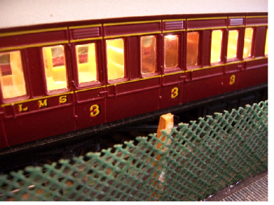
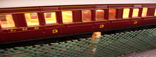
Place the coach on a live track and confirm all is working (Photo 13).
Photo 13 (not actual model)
How To Install Interior Lighting Into Hornby LMS Crimson Standard Period-
ROB’S RAILS 
Article 3 -
© Rob’s Rails 2015