ROB’S RAILS -
Notes:
i) The methods following are specific to the coaches listed above, but apply in general to other marques of coach. Opening up other coaches for access may require different procedures. Check with the service sheet if available. Be careful of dislodging fragile parts when opening coaches.
ii) My Bachmann Mainline coaches and the Hornby Restaurant Car both had plastic wheel sets as delivered, which I replaced with Hornby R8234 metal, 14.1mm diameter, 4-
iii) You may consider using Hornby Pullman coach wheels X9096, designed for use with power pickups for lighting, having one wheel insulated and the other live to the axle. To use these you arrange to have one bogie axle(s) live to the left rail and the other bogie axle(s) live to the right rail and connect the wiring accordingly. Therefore you can have each axle of a single bogie connected so -
iv) Wheel pickups are many and various, ranging from bespoke phosphor bronze wheel/axle wipers, to axle spring wipers, to springy brass/steel wire wheel-
v) The described installation is for running under Digital Command Control (DCC) only, with the lights on all the time.
vi) To have the lights switchable by DCC you will have to install a suitable decoder between the bogie pickups and the led strip.
vii) For operation on DC, a bridge rectifier will be required in the circuit to ensure the lights work in both travel directions.
viii) Details of how to convert the lighting for scenarios vi) or vii) is not covered by this guide.
Bachmann Coach:
1. Unclip the body from the chassis by carefully prising the chassis lug from the coach body slot at one end with a thin bladed flat screwdriver or similar. The body sides will unclip as you rotate the body upwards, whereupon it can be fully detached (photo 1).
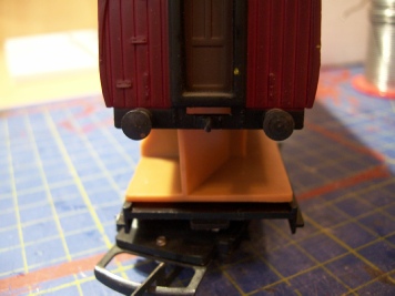
Photo 1
2. At this stage, mark one end of the coach body relative to the chassis, similarly with the seating insert. This ensures that upon reassembly all parts will be correctly orientated.
3. If the seating insert has not already come out, remove it by tapping the lower body on the bench until it releases.
4. The lighting described is modified Ikea Ledberg Type L0911 units. 3 x clip together light bars are supplied with a 12vDC output, mains-
5. Remove the Ikea led board from its plastic housing by pushing in the small clear plastic peg near the ‘socket’ end with a small diameter probe. Slide the board out from the ‘plug’ end. Discard the housing and peg. (photo 2).
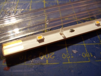
Photo 2
6. Measure the led board against the coach seating insert and trim with a fine saw or knife at the ‘plug’ end as shown (photo 3). Leave approximately 5mm of board past the led to solder a resistor to later.
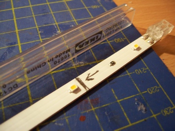
Photo 3
7. In this model, the seating insert partitions fit right up to the coach roof, so we need to recess the led board, using it as a guide to mark up then notch the seating insert to accept the board (photo 4).
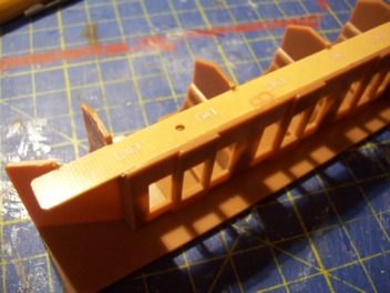
Photo 4
8. Solder 20cm long, thin flexible wire leads to the copper pads at the ‘socket’ end of the led board. Then carefully abrade the white coating at the cut end of the board until the copper tracks are showing. Once cut for some reason the Ikea board does not light all the leds. Investigation shows that in order for all the lights to work on DCC we need to carefully solder a 1K resistor across 2 of the 3 exposed copper tracks at the cut end, i.e. between the centre track, which is very narrow and the left hand track (photo 5).
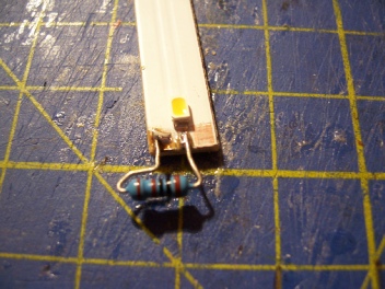
Photo 5
9. Drill a hole in the bottom corner of the seating insert vestibule (which is the angled corridor to the inter-
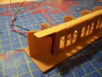
Photo 6
10. At this stage, you could loosely assemble the body and seat insert and connect across the Ikea power supply to assess overall brightness. If too bright, insert a 1K or miniature variable resistor in of the leads in the vestibule area or if just too white dab yellow paint on the leds.
11. Remove one or both bogies from the chassis (depending upon how many pickups you wish to fit) by squeezing the pivot pin and pushing down. I only modified one bogie, as I do not mind flickering lights across points. It is possible to modify the chassis without removing the boogie but it is more difficult, requiring great care to avoid unwanted damage.
12. Drill and slot the chassis adjacent to the pivot boss for the leads (photo 7). This slot must match up with the recess in the underside of the seating insert. Feed the leads from the seat insert through the chassis.
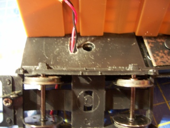
Photo 7
13. Assemble the seating insert into the coach body and clip this assembly back onto the chassis matching up your earlier orientation marks, to ensure the coach windows match the interior and the chassis underfloor components are on the correct side.
14. At this stage for convenience you may wish to carry out the basic install of your bogie pickups away from the chassis (per the pickup manufacturer’s instructions or other information you may have to hand) although most pickups can be installed with the bogies in-
15. Feed the wire leads through the squarish arced holes in the bogie each side of the pivot (these holes show in the circle between the axles -
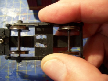
Photo 8
16. Repeat the pickup installation on the other bogie if required, noting that at some stage you will need to splice into the feed wire leads from the first bogie and route them along the chassis and down through the second bogie pivot holes similar to above. You may wish to complete one bogie first and then extend the feed wire leads from there to the second bogie. Secure and disguise these additional wire leads as required.
17. Trim and solder the feed wire leads to the pickups (photo 9), noting that if using both bogies and normal wheel sets, that you must match the wiring side to side or there will be a track short. If using Pullman wheel sets fit them with their live wheels opposing i.e. bogie 1 live wheels left and bogie 2 live wheels right and wire bogie 1 to left feed and bogie 2 to the right feed.
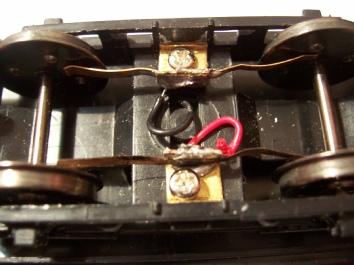
Photo 9
18. Place coach on the track and confirm all is OK (photo 10).
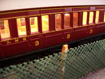
Photo 10
Hornby Restaurant Car:
1. Unclip the body from the chassis by insert a plastic card along each side of the coach working from the middle to the ends.
2. Remove and retain the two small screws securing the seating insert to the chassis. Remove the seating insert complete with its attached steel weight.
3. Mark the coach body orientation relative to the chassis to ensure correct reassembly later. Note that the seating insert can only fit onto the chassis one way.
4. This coach uses a full length Ikea led lighting strip, but you still need to remove the led board from the clear plastic housing as before. This time unsolder and discard the springy plug part, clean off the white coating from the centre track at this end to expose copper and solder on a 1K resistor as for the Bachmann coach method. At the other end, solder 30cm long thin flexible feed wires to the copper pads as before. You need the extra length of spare wire when assembling the coach again.
5. Attach the led strip direct to the centre of the coach body roof using double sided tape, placing the resistor close to one end and aligning the leds as best as possible with the various coach compartments. Now secure the feed wires to the roof at the other end with a dab of glue so they can run down the end wall (photo 11a).
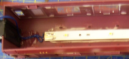
Photo 11a
6. Drill a 3mm hole in the seating insert floor near the end for the feed wires (photo 11b).
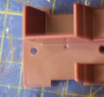
Photo 11b
7. You can install the rest of the modification without removing the bogies if you are careful.
8. From underneath drill a 3mm hole in the bogie frame only, just in front of the pivot point, but avoiding the pivot housing on the chassis above.
9. Now swing the bogie to full arc in both directions and using the bogie hole as a guide drill through the chassis above at each end of the arc swing.
10. From above carefully join these two holes in the chassis to form a slot avoiding any damage to the bogie, its pivot mounting area or the seating insert screw boss (photo 11c).
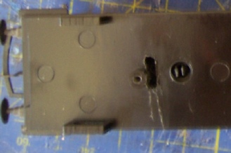
Photo 11c
11. Feed the wire leads from the coach body roof through the hole you made in the seat insert and backwards towards and down through the slot you made in the chassis and then down through the hole you made in the bogie.
12. Screw the seating insert back onto the chassis using the two small screws retained earlier; making sure the seating insert locates correctly with the various mating parts on the chassis. There is an adequate gap between the underside of the seating insert and the chassis for reasonable sized wire leads to feed through.
13. Carefully pull the feed wire leads through the floor gap and bogie as you clip the coach body back into place. Check the bogie has full range of movement without straining the feed wires (photo 12).
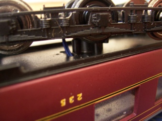
Photo 12
14. Install your bogie wheel pickups of choice, then trim the feed wire leads to length and solder to the pickups (photo 13 -
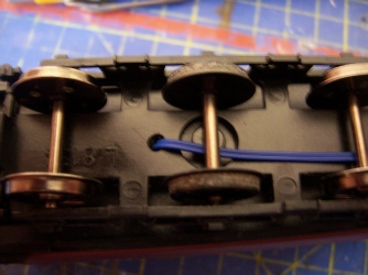
Photo 13
15. If required install pickups on the other bogie and run extension wires from the first bogie along the chassis floor (over or under the chassis as you wish and/or disguise with paint if required). Take note of earlier advice about pickup arrangements for Pullman wheel sets.
16. Place coach on the track and confirm all is OK.

This article describes the fitting of LED lighting to:
Bachmann Mainline, LMS 57-
© Rob’s Rails 2015