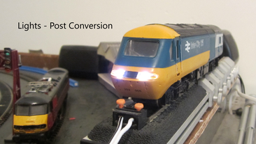
Converting the Hornby Class 43 HST to DCC sound and modification of the directional lighting.
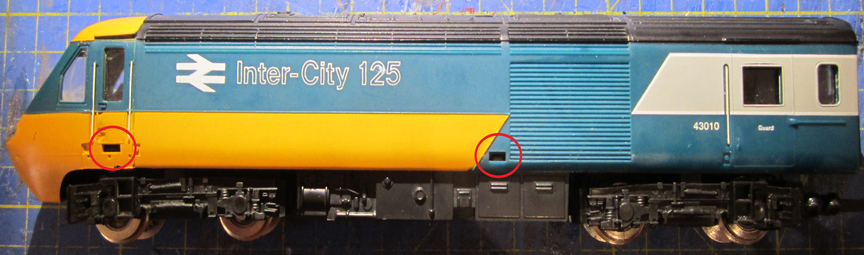
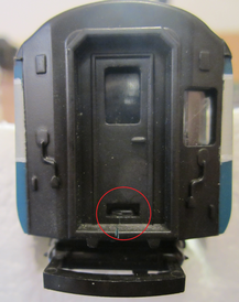
Power car 43010 showing the side body attachment tabs; a further tab is located at the rear end seen below, which is released first. Trailer car 43011 has an identical body and chassis, except it uses twin dummy bogies to pick up power for the lights rather than the Ringfield motor bogie and dummy front bogie used in the power car.
Parts Required:
Qty 2 x 8-
Note: This conversion does not use Pin #3 (F1 -
Qty 4 x 2mm -
Note: Only positive anode 3-
Qty 2 x Hornby TTS decoders and 2 x 8 ohm impedance speakers of your choice. Valenta engine decoders are used as these engines were installed during the livery of these cars. Other make decoders may be installed in lieu.
Qty 3 x X8515 Collector Assembly. This brings the non-
Sundries -
Qty 6 x 1K Ohm SMD resistors -
I use a simple vero-
Circuit schematic:
Note that this schematic is for a double ended loco. For the HST we only use the appropriate connections for each car as stated above.

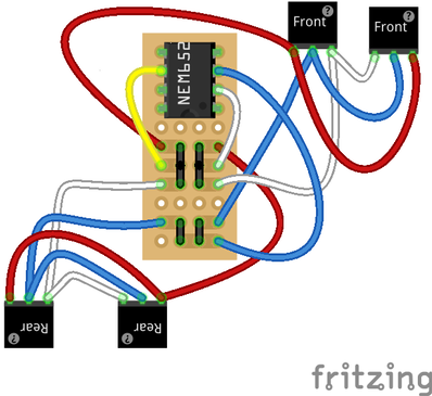
In the diagram below the decoder socket is represented by the over wide NEM652 ‘chip’ which actually only spans the inner pairs of holes. These are isolated by breaks in the vero-
Veroboard:
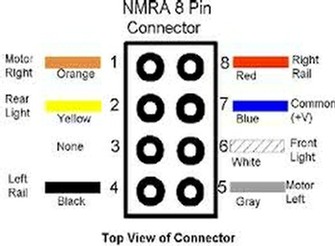
This view is from the NEM652 socket side, thus the copper tracks and the SMD resistors are on the far side. Pin 1 orange is top left of the socket. When soldering the SMD components, link wires and off board connections work from a mirror image of this diagram. Run link wires on the resistor board connecting to the decoder socket pins 2, 6 and 7 marked in the NMRA diagram shown earlier. The actual blue, white and yellow link wires can be made much tidier than shown. Connections to off board components are as shown in the various pictures and described in text. Note that the front lights white is connected to the socket white circuit and the front lights red is connected to the socket yellow circuit and vice-
Preparation:
Unclip the chassis frame from the body of either car by easing out the rear tab shown above with a slim flat bladed screwdriver then springing the body sides apart and removing the rear of the chassis down and out whilst pivoting about the front (pointy) end.
For the purposes of the conversion left and right are as if looking towards the pointy end of each car. Directional lighting wiring and pickup wiring logic may seem to be wrong as a result but remember the trailer car is sitting pointy end facing backwards, hence left and right wiring installation is reversed in this car. Follow the instructions as presented and your directional lights will work correctly at both ends in both directions. If you get it wrong it is easily rectified.
Power Car Conversion:
Note: as you are dismantling the motor bogie it is worth overhauling the Ringfield motor at the same time. This is not detailed here but the process is straightforward and well documented on the Internet and parts are readily available. After overhaul ensure the motor runs freely and reliably on DC using a 9 volt battery across the wheels. You may consider replacing the Ringfield motor with a DVD can motor.
Remove the power car body as above.
Disconnect all wiring from the model by pulling off the spade connectors or de-
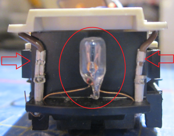
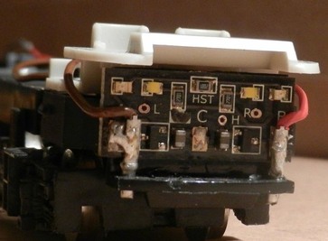
Unplug the headlight bulb wiring (arrowed) and remove the bulb and wiring. Retain for spares or discard.
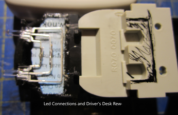
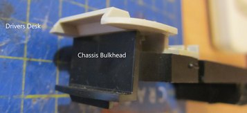
Pry the driver’s desk from the chassis frame (shown inverted in the picture below). This needs to be reworked by cutting out the shaded area to provide clearance for the leds as fitted here. It may be possible to use 3-
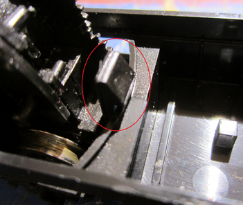
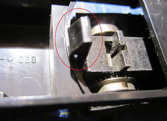
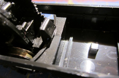
Unclip the motor bogie frame from the chassis frame by pressing the clip shown below inwards to allow the bogie to drop out of the chassis frame.
Repeat for the dummy bogie.
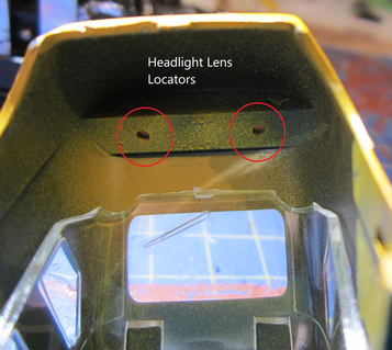
From the inside of the body carefully press out the headlight lens (below). Keep the lens safe for later.
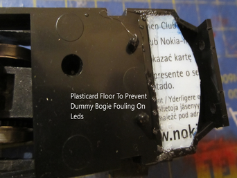
Make up a plasticard rubbing plate to fit in the front of the dummy bogie area. This is to prevent the dummy bogie clip snagging on the leds we will fit later.
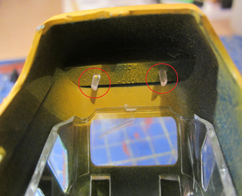
Temporarily refit the body to the bare chassis frame. Using a small drill or scribe through the holes in the body to mark the frame bulkhead. Remove the body again and open up the marked holes in the bulkhead to 2 mm for now. Do not open up the holes in the body.
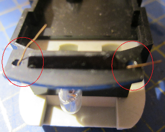
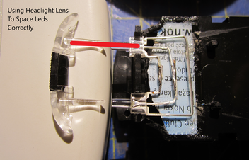
Using the led as a guide, mark and cut slots in the frame bulkhead to accept the square body of the leds. Use the headlight lens prongs to ensure you get the leds at the correct spacing. Do not position the led ends past the forward end of the chassis frame or they will foul on the body.
Place the leds in these slots as shown then bend each leg to match the connection pattern shown above and solder. Check with the drivers desk for adequate clearance. Check that you have the correct legs connected to each other before soldering, centre to centre, white to white and red to red. Check with the headlight lens that the leds are still correctly aligned for width. I had to trim my desk to clear the led legs and attached wires. It should be possible to improve upon this installation using 3 pin led sockets glued to the plasticard insert and run the wires to the sides as per the filament bulb wiring, linking them in the chassis area.
Solder blue, white and red wires to the leds i.e. long centre leg is common positive (blue wire), mid length leg is switched negative for red lights (red wire) and short leg is switched negative for white lights (white wire). Run these wires back and connect to the resistor board front light connections described earlier.
Note that no attempt is made to permanently fit the leds direct to the body as this could hamper body removal for maintenance.
If preferred wire each led separately in parallel back to the board rather than using the ‘5-
At this stage it is wise to test the leds work correctly and thus also prove the resistor board. Use a 9v battery with the positive wire plugged into the blue (+) pin of the socket and in turn plug the battery negative wire into white and yellow pins of the socket (with blanking plug removed). If all is well you will have white lights and red lights, therefore the driver’s desk can be refitted (as below). I used a little plastic cement at the bulkhead join as the desk was slightly weakened by the rework.
Once the motor and pickups have been attached to the socket connections on the vero-
Later we shall make the headlight lenses fit snugly against the Leds.
Motor bogie modifications:
Replacing traction tyre wheels:
Unclip the motor housing from the motor bogie frame by carefully prying with a flat bladed screwdriver whilst applying upward pressure to the motor. Note which way the motor housing fits relative to the bogie frame.
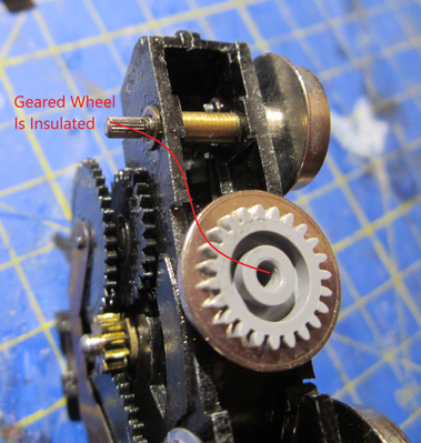
Pry the motor bogie traction tyre geared wheel from the axle and remove the other wheel and axle from the motor housing. Remove the geared wheel from the new solid tyre wheel (same part number wheel as is used on the dummy bogie -
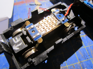
Power pickup:
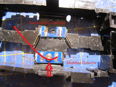
Modify an ESU 50700 coach lighting power collector (or similar DCC Concepts item) as shown and screw to the motor bogie plastic frame (arrowed). Note the contacts are reversed so as to offer the ‘pipped’ side of the wiper to the front face of the wheels. Solder a red wire (shown) across both solder pads on the collector and long enough to reach back to the NEM652 socket pin 8 and onwards to connect to the front bogie pickup.
Note: these power collectors are meant to be used across an axle and are thus isolated side to side. For use fore and aft as here this isolation gap needs to be bridged by the feeder wire.
Recover a length of existing wire removed earlier (preferably black) with a small spade terminal, long enough to reach the NEM652 socket pin 4 and attach the spade terminal to a lug on the motor housing (either front or back), ensuring any paint is removed from the contact area. The connection is not ideal but all we have without drilling and tapping for a screw connection as seen on other Ringfield housings. This wire will also connect onwards to the other wire from the front bogie pickup.
Solder (or use spade terminals) orange and grey wires to the motor brush terminals allowing adequate spare length. (I didn’t have these colours so I used yellow and blue instead). If later the car runs contra to the selected direction just swap the motor connections over.
Clip the motor bogie back into the chassis frame feeding all the wires towards the NEM652 socket.
Solder the motor brush wires (to pins 1 and 5) and power pickup wires (to pins 4 and 8) to the socket pins (indicated) matching the diagram.
Dummy bogie modifications:
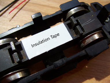
Place a piece of insulating tape over the dummy bogie live chassis and glue in place the new collector wire assembly (part X8515) on the bogie chassis. (Ref service sheet 205 or 266).
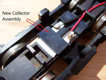
If you can’t find the later style power collectors then it is possible to make your own from a bit of veroboard and a pair of ESU collectors as shown below. The picture shows the collectors before being clamped down for final soldering. The vero-
Clip the dummy bogie back into the chassis and solder the pickup wires to the matching wires from the motor bogie pickups at the NEM652 socket (pins 4 and 8) ensuring continuity of front left wheels to rear left wheels and front right wheels to rear right wheels.
At this stage you can fit a decoder blanking plug or link wires and test the power car motor on DC.
TTS sound:
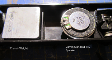
If required replace the standard 28 mm round speaker with the speaker of your choice, by un-
Tip: tape the speakers to the bench whilst soldering.
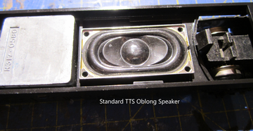
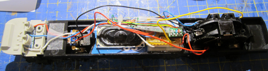
Plug the TTS decoder into the NEM652 socket taking care to align pin 1 of the decoder plug with the orange wire of the socket. Position and secure the speaker as required, noting that for best sound quality the front and back of the speaker must be mechanically isolated from each other, usually by use of an enclosure. Position the speaker facing up or down as desired but if down facing drill small holes in the fuel tank/battery box floor to let the noise out. I opted for the oblong speaker facing up and will drill out the exhausts to allow the noise out.
I used an old store card as my speaker platform.
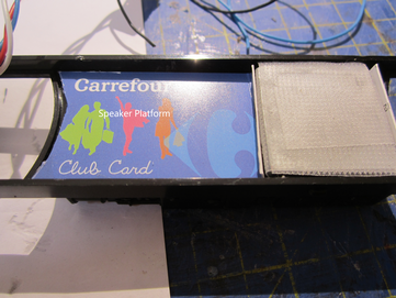
Once finally wired up and tested seal the speaker into place for best audio performance.
Completing the lighting:
Place the body fully back onto the chassis making sure the decoder and wires, etc are not trapped by the body ribs, then offer up the headlight lens to the body. It will probably not fit in fully to start with, so trim 1 mm at a time off the end of the mounting prongs until the lens fits snuggly into the body. Once happy with the fit a tiny amount of glue can be used around the edge to secure it in place.
If it is wished to have more prototypical lighting then a Black-
TTS decoders are limited to basic directional lighting hence the use of my basic single dual-
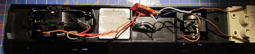
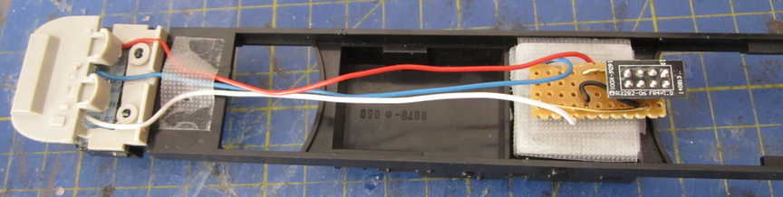
Finally it should look a bit like this. Note the use of blue and yellow wires for the motor connections as I didn’t have any orange and grey wire.
Trailer Car Conversion:
The trailer car conversion is almost identical to the power car except we modify the power pickups of both dummy bogies as described earlier for the power car dummy bogie.
The lighting is installed as above, except this time we use the rear lights and omit the front lights shown on the diagrams.
As the trailer car when running forward is pointy end at the back, hence left becomes right compared to the power car. All we need to do is swap the wires at the bogies.
Addressing the decoders:
Place the power car on the programming track and allocate the address of your choice.
Place the trailer car on the programming track and allocate the same address as the power car if you want both sets of functions to operate together or give it a different address if you want to control each car’s functions separately.
Some controllers may require you to also have the power car on the programming track to act as a load when programming the trailer car. See your controller manual. A temporary load can be achieved by hooking a 100-
Operation:
Both decoders will correspond to the same address if that is how you set them or to their own addresses if set as individuals.
Switch on directional lighting using F0 from your controller function. Switch on at both decoders if set for separate control.
When the locomotive is selected forwards the power car will move forwards and show white lights whilst the trailer car will show red lights. If the direction is incorrect for the selected loco movement then swap the motor brush connections around in the power car.
If the trailer car lighting logic is incorrect swap the wires over at the bogies, noting that the trailer car direction must also be swapped to change the lights. If both decoders are set for the same address this happens automatically.
When the locomotive is selected to move in the reverse direction the trailer car will show white lights and the power car red lights.
TTS decoder actions and sounds are controlled using Function numbers listed in the TTS decoder user manual.
If necessary adjust CV150 to value 1 (regime 2) and/or CV151/152 (regime 1) or CV153/154 (regime 2) to suit the running characteristics of the Ringfield motor.
Rob Honnor. Sept 2018 v1.0 Class 43 HST-
Oct 2018 v1.1 Added details.
Hornby R 069 / R070 -
This article details conversion of the early Hornby R 069 and R 070 Class 253/43 HST models to DCC with Hornby Twin Track Sound (TTS), basic dual colour directional lighting and improved track power collection in both cars.
The conversion incorporates an 8-
Reference should be made to Hornby Service Sheets (SS):
SS108 and SS205 -
SS106 -
SS420 -
SS332 -
ROB’S RAILS 
Article 10 -
© Rob’s Rails 2018