ROB’S RAILS -
Installing sound in a Hornby R1077 Pannier Tank
This article describes fitting a DCC sound decoder to a Hornby R1077 GWR Pannier Tank running number #2728. This model is not DCC-
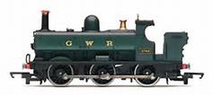
R1077
Fitting sound to a Hornby R3122X DCC-
The critical dimension is that the speaker enclosure base must sit flat on the main body sidewall steps so that the body top will clear the speaker, therefore the decoder mounting must not intrude into this space. Check with the body in place and the tank top removed.
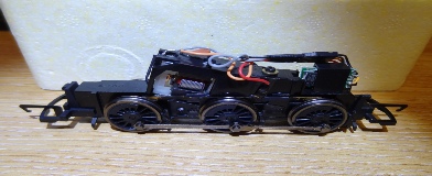
R3122X #2773 Chassis (picture reversed from original)
There is insufficient room to install a standard DCC decoder socket in locomotive #2728 so the conversion is hard wired. It may be possible to install a smaller 8-
The decoder used is a very early Hornby TTS with the standard 28mm round speaker and enclosure. The sound set is of no specific locomotive, with many different whistles and the chuff rate seems to suit the Pannier. Don’t ask where I got it from – the only answer you will get is “...from The Tooth Fairy”.
Remove the coal load by turning the loco upside down and using a thin probe through the hole(s) in the back of the chassis push out the coal load. It is held by a central spigot on the back edge. Mine just fell out.
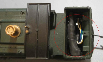
Decoder Stowage, Coal Load Spigot Hole and Probe Access Hole(s)
Remove the body as follows – from the top of the coal bunker using a flat screwdriver blade carefully press the rear hook on the chassis forwards and down to release the body. The body will rotate about the two front hooks and can be carefully removed. See pictures of Back Hook and Front Hook below.
Back Hook
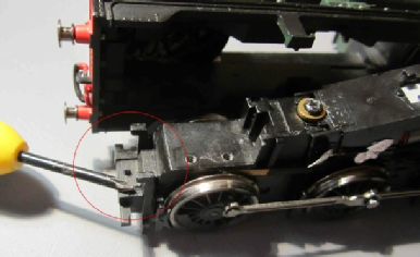
Front Hooks
Modifying the body -
With the top off, trim the two corner posts flush with the main body floor and drill a 3.5mm (max) diameter hole through the funnel to let the sound out. Also remove and trim to length the two body side weights to make room for the speaker. The weights are just stuck down, so pry them off, trim to length and refit after mounting the speaker and routing the wires. Trim the top slab spigots flush also.
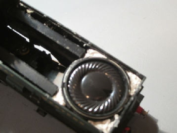
Speaker Installation
The speaker is mounted in its usual plastic enclosure to maximise performance, (but with the two mounting lugs trimmed off). It sits flat onto the floor of the body sides. White blu-
If you don’t have an enclosure you can make one for a 28mm diameter speaker from the bottom end of an empty Humbrol plastic paint pot. The speaker wires need to be extended to reach the decoder so do this before mounting the speaker. Either unsolder at the decoder or speaker or cut the wires mid-
Run the speaker wires down the side (I used right hand) of the body weight area and into the coal bunker area, ready to reconnect to the decoder pads if your soldering skills are up to it, or more simply reconnect to the existing speaker wire stubs from the decoder. I had to trim the rear under-
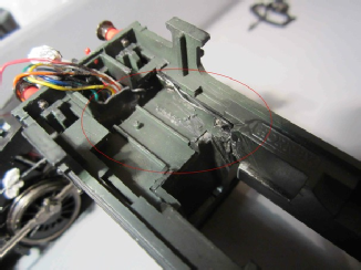
Body Modification
Unsolder all wires and capacitors, etc from the motor terminals and wheel pickup strips, noting that as the lower motor terminal is fairly inaccessible, I opted to cut this wire about 1cm from the terminal, then solder the new decoder wire to it and sleeve the joint. If retaining the 4-
Now the only real tricky bit – the sleeved TTS decoder only just slots into the coal bunker and the wires have to come down through into the chassis area. This means working with the decoder in the upper bunker area and the body close to the chassis. You need enough slack wire to be able to work and to manoeuvre the decoder into place later.
The sound decoder 8-
Wiring up the decoder -
Pickup Wiring
There is very little room between the chassis sides and the body so make sure your soldering is neat and the pickup tangs are pressed flush against the plastic motor block.
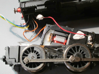
Solder the orange (motor top) and grey (motor bottom) decoder wires to the motor terminals using the lower terminal extension method as noted earlier.
If you have not already done this reconnect the speaker wires and sleeve the joints.
Secure all wires as best as possible out of harm’s way using blu-
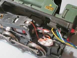
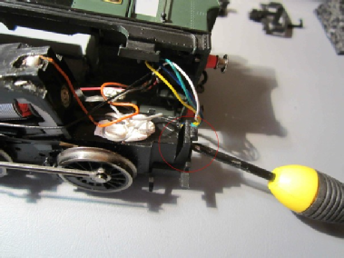
Motor Wiring
Test the installation at this stage with the body loose, including for correct motor direction and sound functions. I have a rolling road so it was a simple case of putting the chassis on the rollers, propping the body up safely and testing it all worked. Don’t expect too much quality from the sound with the body off.
When you are sure all is OK, re-
My decoder is encased in heat shrink tubing which is closely trimmed at each end. There is not much room in the coal bunker, but the decoder will rotate into place and slot down nicely if you get the lumps and bumps the right way round. The spare wires can be packed into any gap. See earlier picture.
All that remains to be done is to trim the inside of the coal load if necessary to clear the decoder and drop it back into place. The tank top clicks into place at the back and needs a bit of glue or double sided sticky pads or blu-
Re-
© Rob’s Rails