The procedure totally dismantles the unit, but you only need to dismantle as much as is necessary to access those parts you wish to work on.
This information is provided in good faith, but as I have no idea of your skill levels it is assumed you know what you are doing and that you work on your eLink at your own risk.
Be aware that opening the case and/or making changes or attempting repairs to this unit will invalidate any warranty on your eLink and may also preclude any future chance of Hornby being able to repair or even update the unit. This also applies to any eLink bought second hand, whether working or not, as the previous owner may have opened the case or attempted repairs.
This controller has no user controls and can only be used in conjunction with Hornby Railmaster Software.
To date there have been several cases of eLink failure reported on the Hornby forums. Mostly these reports have been about eLink feeling hot, making buzzing noises and/or having communications problems with the Railmaster software. There is a heavy duty resistor (R86) inside the eLink generating heat so running hot is not a fault.
Dismantling:
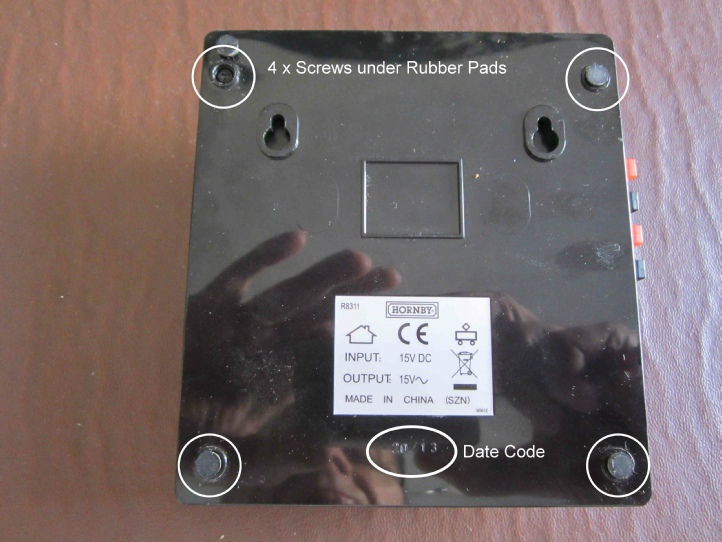
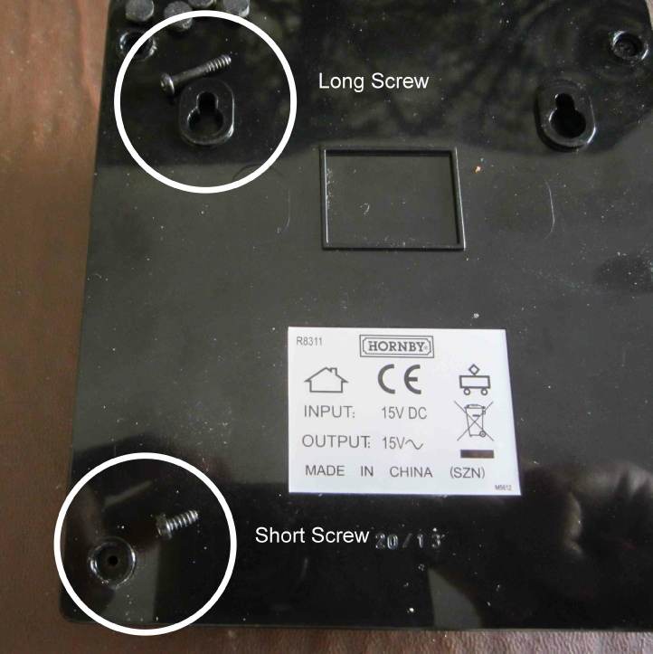
There are 4 x security screws (2 x short and 2 x long) hidden under the stick on rubber feet in the lower case. You will need a triangular bit to remove these screws, although at a push a suitable size hex drive will work, but be aware the screws heads are soft and easily damaged.
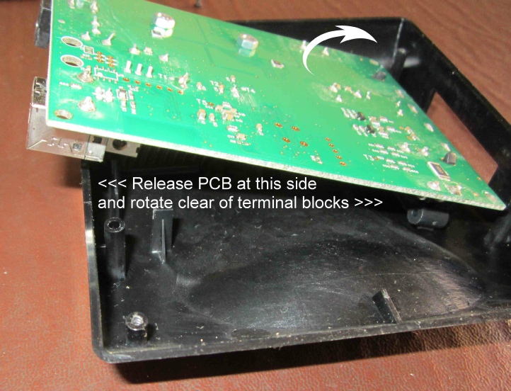
The lower case then unclips (4 x tags) from the upper case. Start this at the USB/DC Input Jack side and rotate the case away clear of the terminals.
You can then rotate the circuit board out of the case in the same manner.
There are relatively few components on the circuit board. The major items are shown below.
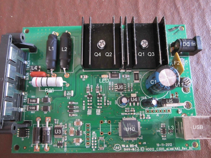
Components:
Code Description Part Number Purpose
F2 3-
F3 1.1-
L3 Common mode choke 220R ACM2012-
L4 Common mode choke 60R CM1812R600R-
L6 Common mode choke 60R CM1812R600R-
L11 Common mode choke 680R Ind Moled DC input
U3 Quad differential comparator LM339N Railcom
U4 3V Voltage regulator LD1117S33TR LDO DC input
U5 12V Voltage regulator L7912 CV DC input
U6 Dual op-
Q1 and
Q2 Dual mosfet NTD5867NLT4G Track output
Q3 and
Q4 Dual mosfet FDD6637 Track output
Q8 and
Q9 Dual mosfet IRF7509TRFPBF Programming output
Faults:
There are two sources of heat on the circuit board – the heat sink for the Track output components Q1 to Q4 and the 3W resistor R86. The upper case is ventilated but it is normal for this heat to be felt during normal operations.
If the unit is dismantled it is worth removing the black extruded aluminium dual heatsinks, cleaning off and reapplying heat transfer compound and ensuring the heatsink attachment screws are firmly tightened.
Noise – there is no transformer in the eLink so any noise must be harmonics from circuit components, probably the inductors.
Communications problems with Railmaster – these have been fully covered on the Hornby forums and the fault usually lies in the .ini file user setup. If the forum advice is followed communications are usually restored. Anti-
Firmware update:
Any firmware update is automatically taken care of by Railmaster checking at startup and applying the update if required.
If there is any problem with the auto-
Acknowledgments:
Many thanks to Ken Wards in the Hornby Research and Development Department for his help in providing part numbers for the circuit board codes quoted in this article.
RH/eLink/Nov2017/v1.1
ROB’S RAILS -
Hornby R8311 eLink DCC Controller
This report details the procedural teardown of a Hornby eLink DCC Controller, highlights any parts that are known to have gone faulty, tells of their physical circuit board code, identifies their original part number and where applicable provides an equivalent part by supplier code.
© Rob’s Rails 2019