Converting the Hornby Elite DCC Controller to install a backlight.
Source of parts:
www.elwirecraft.co.uk
Or the panels can be obtained direct from
http://elpanelandtape.co.uk/el-
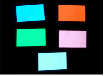 Panels are available in many sizes and colours.
I used a blue one.
 The driver needs to be 12v and must be the smallest one they supply for direct connection to fit inside the Elite case.
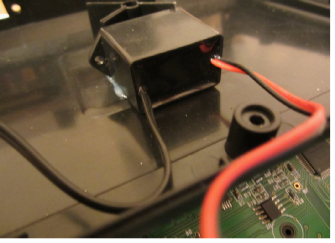
Ask for the waterproof one, size 29mm x 19mm x 24mm for 12v, without a switch or battery box, as shown here.
Or you can just specify the kit for the Spectrum radio control handset which includes a panel big enough for the Elite screen, again you must specify the 12v driver and your choice of colour.
Modification Procedure:
Remove the two speed controller knobs – they just pull off.
Now remove the nuts and washers securing the speed controller switches or encoders as they are more accurately known.
The screws holding the Elite case together have a triangular head recess but if you don’t have a triangular bit for your screwdriver then an allen key will do at a push.
Remove 5 x screws from the lower case. Remove 4 x screws from the back panel and a further 2 x screws that go up into the top panel from the back panel.
The top pivots away from the lower case clearing the terminals as you go. Put the lower case to one side.
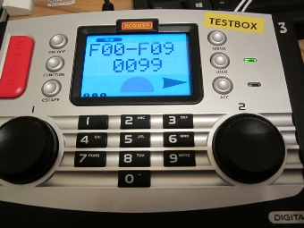
Be aware that when dismantling the unit the keys are all likely to fall out of the case so take note of their locations and orientation (they are keyed) or refer to a picture of the Elite above.
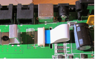 Remove the white ribbon cable for the screen by releasing the clamp clip – prise each end of the darker part loose from the holder and the ribbon will slide out.
Release the two black plastic detent clips at midpoint either side of the pcb and the main board will lift away taking the two encoders with it. Be careful to slide the ribbon cable clear as you go.
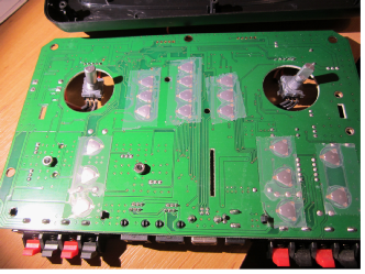 Lay aside the main PCB taking care not to disturb the sellotape holding the triangular button contacts in place.
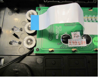 Referring to the picture remove the four cross point screws holding the screen pcb in place. Take care not to disturb the soft black keypad area just below it, else all the buttons may fall out.
Carefully twist straight the six tags holding the screen frame to the screen PCB to align with the slots and remove the frame from the screen.
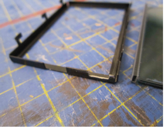 The bottom right hand corner of the frame has to be modified by way of a slot for cable access as shown.
The screen is usually stuck to the pcb by the zebra connectors but it has to be pried off. There is a zebra connector along each long edge. These should be cleaned both sides using IPA and left to dry. Cleanliness of this is paramount else screen corruption can happen and will not be found until it’s all together again, requiring further dismantling and cleaning, etc. Likewise clean the matching pcb pads.
For interest the way these connectors work is they are alternate bits of insulating and conducting rubber – one side of this stack connects with the PCB and the other side with the screen, so alignment is not critical as the elements find their own match.
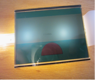 The screen has a white layer overprinted with a part number which will shine through as seen here, so this layer needs to be removed unless you can clean the number off. See picture for the problem.
Now for the really tricky bit -
Assemble and test the ELP as supplied using the driver box fed by a 12vDC source. Watch your fingers on any bare edges of the ELP as the AC voltage whilst not lethal isn’t nice. Work out which edges you are going to trim (Important -
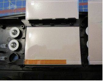 This picture shows the panel cut to fit but with the original connector as supplied interfering with one of the buttons. See later for rework of this connector.
 Trial fit the ELP making sure the side that lights up faces the back of the screen. The ELP has its terminal elements attached to the perimeter (silver stripe and brown lines) so avoid cutting these off and position these to the bottom of screen as the Elite outer screen mask is deeper here and will hide any loss of light better. Now trim the ELP to fit making sure the connector aligns with the ACC button and that the slot you had cut in the screen frame also aligns to allow the wire to pass without affecting the ACC button and that the ELP will fit inside the frame without affecting the zebra strip.
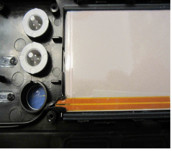
As stated earlier the connector on the ELP as supplied is in the way of the ACC button so it has to be cut back per the instructions on the EL website to fit like the photo above. Again it is a case of reading the instructions and separating the various layers, then re-
The ELP is sandwiched by the frame and the screen against the pcb. Place the zebra strips in place onto the pcb, then the ELP between them, then the screen and finally the frame. Secure the frame by twisting the six tags. At this stage we can test the ELP but not the Elite screen yet for corruption so press on as follows fingers crossed.
 Place the screen pcb into the Elite top case with the ribbon cable as shown and feed the wire past the ACC button. Secure the pcb with the 4 x cross point screws and secure the wire with hot glue as shown.
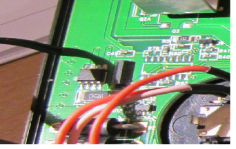
 Place the main pcb back into the top case whilst feeding the ribbon cable through its slot and locating the encoders as you go, making sure you feed the ELP wire out to the side as shown. Click the pcb into place.
Turn the case over and press each and every button whilst listening for them to click. If all is well, slip the ribbon cable into its holder and push the clip back in to secure it. Refit the encoder washers and nuts and replace the knobs.
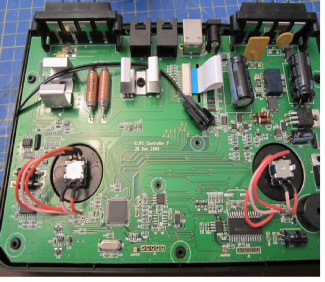
Hot glue the driver box into the lower case after trimming adjacent to the X support if necessary. – see picture at top of page 1.
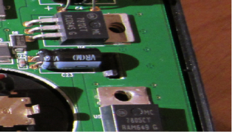
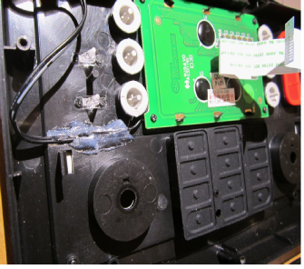
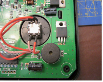 Connect the the driver box black wire with the plug to the matching socket on the wires from the screen. Route excess wire around the pcb and secure with hot glue if necessary. Route the driver box red/black wires to the component marked U5 on the circuit board right hand corner. Trim the wires and solder to the legs of U5 in the picture. The legs are left 12v, centre 0v and right 5v. Connect red to 12v and black to 0v.
Reassemble the lower case to the top case securing with the screws from earlier.
Power up the Elite with the LOCO button pressed. Release when you see Hornby on screen. If all is well the screen will light and all the screen characters will be correct then it will say EE Pass. If not you will have to dismantle and clean up the zebra strip connections again. Power the Elite down and up again for normal use.
If you had to remove the white screen backing and depending upon the colour ELP you chose the screen may be too bright, so you may wish to temporarily splice a variable resistor into the red lead and determine a suitable value resistance value to solder in permanently.
Note: the reason for choosing 12v from within the Elite is that it does not appear to be used for any critical function, whereas the 5v pickoff is mainly used for USB circuits and it was considered to be unwise to deplete these circuits which are used for talking to a PC for updates of the Elite firmware and for use by model railway control software such as Hornby Railmaster.
I hope you enjoy your new brighter Elite screen.
Rob Honnor. January 2017 v1.0.1 Elite Backlight.
ROB’S RAILS 
Article 8 -
Hornby Elite -
This article is about installing an electro-
These panels operate from AC voltage so a driver box is required to convert the Elite DC supply to AC. The smallest driver box available is needed to fit inside the Elite case.
12v is chosen for the supply as this is readily available within the Elite circuits.
ELPs are available in several colours including white, so the choice is yours.
Panels and drivers are available separately or you can go for a kit that is made for a Spectrum Radio Control handset, which has a similar sized screen to the Elite. The kit price is about the same as the separate components -
© Rob’s Rails 2015