Introduction:
Each lamp has 2 bi-
Switching:
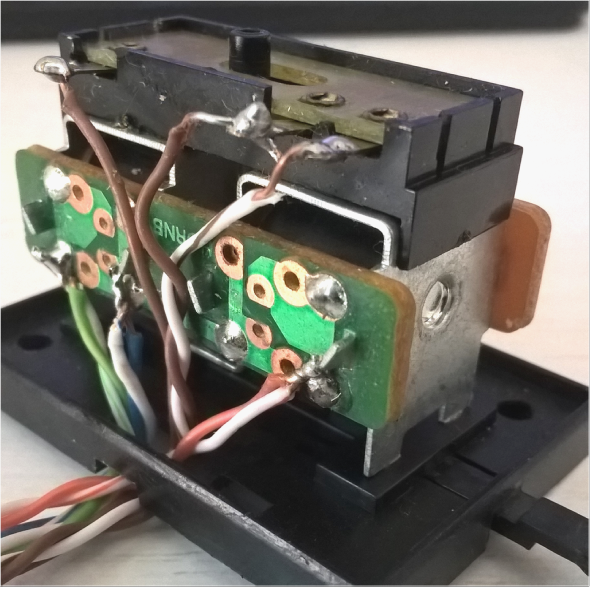
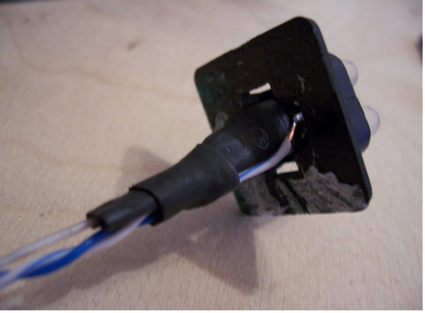
These lamps are operated by a simple slide switch attached to each point motor as pictured below, so the lamp accurately reflects the actual state of the point, not the state of the toggle switch that asked for a turnout position change. Other types of switch may be used providing they are activated by the point or point motor, not the toggle switch on the control panel.
If you are using small surface mounted point motors such as the Hornby one shown later, or the Peco side mounted motor, which do not have the facility to mount this type of switch, then you can modify the switch by trimming off the vertical lug (shown above) at each end where it clips to the motor and then glue the switch directly to the underside of a point as shown below, taking care to get it exactly central.
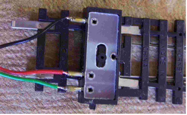
To mount the switch as above obviously a suitably sized cutout will have to be made in the baseboard or underlying ballast area.
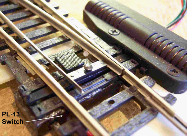
To operate the switch press a Hornby track pin (which is exactly the right interference fit in the switch) through the point tie bar into the bush on the switch slider as shown below. Do not press the track pin too far into the tie bar as it can bind the point mechanism.
Variants:
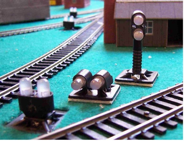
The LEDs in the basic indicator lamp discussed in this article have been mounted vertically as shown. This is obviously not prototypical, but thus configured I can easily see them from my operator’s position and also they are not restricted to uni-
Parts:
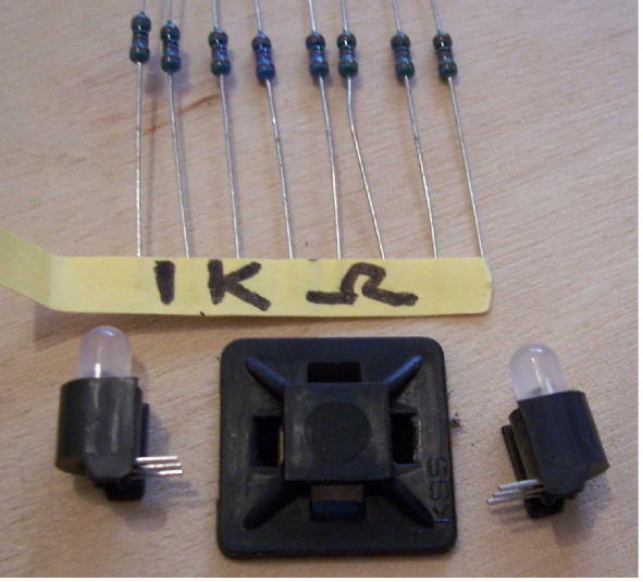
I have used 5mm Diameter 3-
The centre leg of these LEDs is a common cathode to which a resistor must be connected in series to limit the current felt by the outer anode legs, which light the red and green elements respectively. By joining the red leg of one LED to the green leg of another we can have switchable red/green or green/red combinations for our points to indicate which route has right of way.
If you want to have these indicators attached to a pair of points that have been link-
Green and Red LEDs have different characteristics and if powered at once the red will be dominant, so in order to balance these biases correctly to achieve the amber colour, you have to modify the build to provide separate resistors in each of the colour (anode) legs rather than just use a single common resistor in the centre (cathode) leg.
Due to the different forward voltages and operating currents of the two colour elements (see your LED specification sheet), these pairs of resistors need to be of differing values to balance the characteristics of the red/green elements.
A simple way to find these values is to put a ‘standard’ 1K resistor on the ‘weaker’ green leg and a suitable range variable resistor (potentiometer) on the ‘stronger’ red leg, then adjust the potentiometer until you get the correct shade of yellow/amber you like with both legs powered up and you can then read the value set on the potentiometer with a multi-
You can find on-
Parts List (per lamp) for Basic Signal Lamp:
1 x Maplin cable tie base -
2 x 1K Ohm resistor. The correct calculated resistor value for these LEDs should be around 1/3 to 1/2 this value at 12V-
For the amber capable version you will also need 2 x whatever value resistors you determined earlier.
2 x PCB mounting 5mm Bi-
Suitable heat shrink tubing – available from Maplin and other sources and in many sizes.
For the post mounted version -
Build Method:
First bend the 3 -
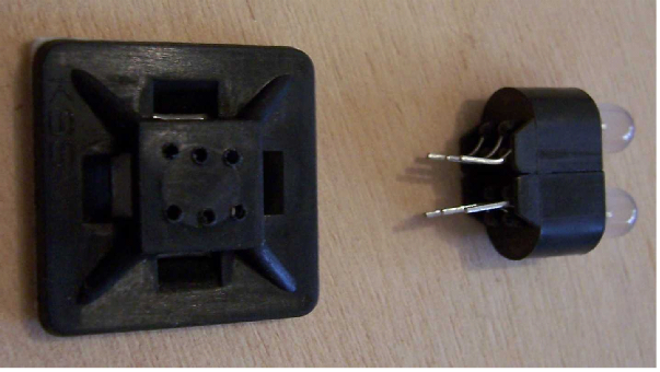
For the basic lamp variant using the LED legs as a guide, drill 6 x 1mm diameter holes in the base. The base is supplied with double sided tape on the bottom. This should be removed to improve access for soldering later, as the completed unit can be fixed to the layout baseboard later with a drop of glue after correct orientation is established.
You will need to drill a 5mm diameter hole in the base-
For the other lamp variants either drill 6 x 1mm holes in a row to suit the horizontal side by side arrangement or a single hole to suit the post for the vertical stacked variant.
At this stage it is wise to use an LED tester to check you have the LEDs correctly oriented in the housings, so that when you connect the legs together you get the correct colour opposition – one green and one red. As you are gluing the housings back to back they should be OK as supplied, but it is wise to check now rather than find you have 2 x reds and/or 2 x greens.
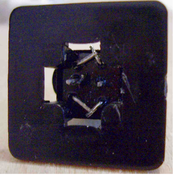
Assemble the LED block to the base and from underneath carefully trim, then bend the outer pairs of legs at an angle as shown below to secure the LEDs and to give yourself a bit more elbow room to solder. Leave the centre pair of legs straight for the resistors to connect to. Run a little superglue into the joint between the plastic housing and the base-
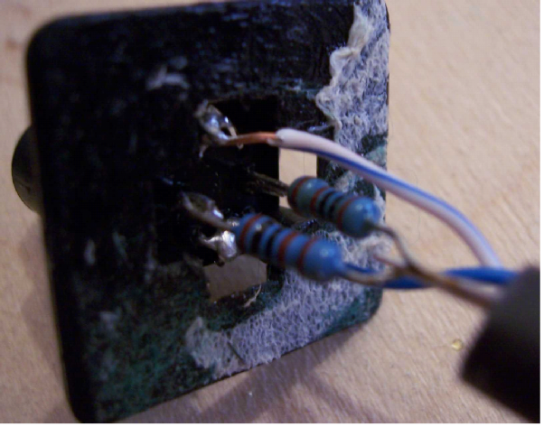
Next as shown below, solder a resistor to each centre leg, then solder the free ends of the resistor leads together and connect to a length of cable that will go back to the power source negative terminal by way of a collector bus, not forgetting to slip on a piece of heat shrink tubing onto the wire first to insulate the resistors' joints.
Solder a lead to each connected pair of outer legs, protect with heat shrink tubing and feed these wires back to connect each one to its associated point motor mounted PL-
For the other lamp variants connect the equivalent outer legs together and attach resistors to the inner legs then feed wires to the base as before.
In even of wanting the amber/yellow build requirement then obviously solder resistors to the outer legs ensuring the correct value goes on the correct leg.
Slip the wires through the hole in the base-
Solder a wire to the PL-
Tip1: When making LED connections back to the PL-
Tip 2: If you forgot to do Tip 1 and the logic is wrong, then just rotate the lamp unit 180 degrees before securing to the baseboard.
More LEDs of suitable colours can be added to make 3 or 4 aspect or even feather signals, but although the basic wiring is similar, the actual switching is more complex than can be covered here.
Revised:
Rob Honnor -
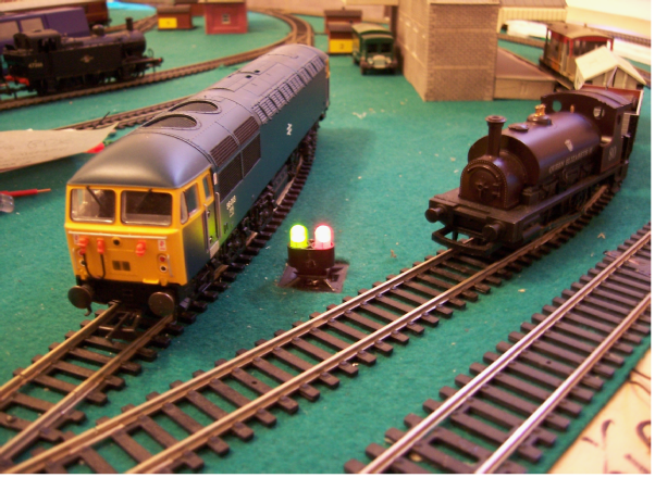
Turnout Indicator Lamps:
I have used LEDs on mimic panels previously to indicate point positioning as they were switched, but a layout may be more suited to having indicator lamps in the near vicinity of each turnout as shown below.
This article details how to make dual LED indicator lamps that can be placed on your layout near each junction to confirm that a point has actually moved to its selected position.
The lamp switching is based upon solenoid point motors being used with simple clip on Peco PL-
Other solenoid or servo type point motors may have built in switches that can also be used.
If you use surface mounted point motors that do not allow attaching this type of switch then I suggest an alternative method in the text.
ROB’S RAILS 
Article 5 -
© Rob’s Rails 2015