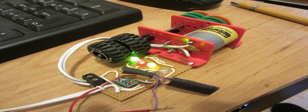
The basics of the test rig is a piece of Vero-
Onto this board is fixed a motor gearbox unit to provide a load on the decoder to allow programming as well as indicate direction, a socket to easily connect the decoder to the rig, quantity 4 x LEDs (5mm diameter) of various colours, quantity 4 x 1K resistors and 3 x 2-
You will also need a few short lengths of equipment wire to act as board links.
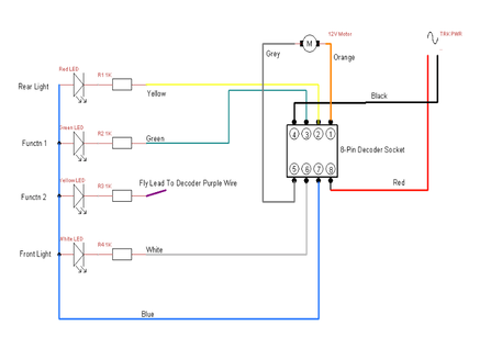
This is the circuit diagram:
This the Vero-
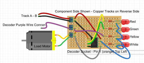
After cutting the copper traces, solder the 2 pin cable connectors and the 8-
I used single colour white and red LEDs to simulate the locomotives front and rear directional lighting respectively (under control of decoder Function-
A green LED simulates decoder Function-
The decoder blue wire (+ve) is fed in common to the anode side of the LEDs. There is a connector on the board to allow the free purple wire of a decoder to be easily attached for testing as this does not go through the standard 8-
Connect the motor gearbox unit to the board using the connector. This allows you to easily disconnect the motor gearbox and connect any other decoder controlled device you want to test for your layout, such as a signal, light, windmill, or fairground ride, etc.
Solder on all the link wires and connect a pair of fly-
Initial Setup:
Install a known good decoder to the 8-
Using your DCC controller initialise the decoder to its basic default settings by writing value 8 to CV8 (Hornby and some other decoders). This will set such things as speed steps, lighting functionality and motor direction to default normal.
Now switch the test rig to the TRACK terminals of your decoder and then run the loco in a forward direction. Mark the motor gearbox unit FWDs to accord with this direction. My gearbox output shaft has an old model car wheel mounted to it marked to more easily show movement.
Check by selecting F0, F1 and F2 in turn that the LEDs light up in the correct sequence and logic. I.e. white LED lights up when F0 is selected and locomotive is going forwards, red LED lights up when reverse is selected. Green lights up when F1 is selected and yellow lights up when F2 is selected.
The test rig is now normalised and when you plug in a new decoder or one you want to test you know that the direction of the motor and the logic of the LEDs is correct and you can therefore easily check the new decoder. At the same time you can give it its new address and check such things as sound functions work correctly.
© Rob’s Rails 2015
ROB’S RAILS 
Article 4 -
This article details how to make a simple test rig so that you can carry out pre-